
Every seasoned embedded systems engineer faces at some point of their career a problem about needing to put a header to their built firmware image binaries. This header usually contains at least information about what device the image is for and what version number the image is. Checksums are also common.
There are multiple ways of implementing the header. One solution is to just glue it on top of the image and peel it off while updating the firmware via IAP or external programmer means.
Another approach is to place it actually in firmware flash, to a known location, possibly even start of the image, but use a bootloader to jump past the header.
There is however yet another solution I’m going to demonstrate. It is about generating the header template directly into the flash image, and even surprisingly in a way that the MCU can start executing actually from the beginning of the header (template). An external tool is used later to fill in checksum data.
But before continuing, heres a big fat warning:
WE ARE MANIPULATING VECTOR TABLE OFFSETS WHICH IS CONSIDERED DANGEROUS PRACTICE REGARDING ULTIMATE RELIABILITY OF THE RUNNING CODE. YOU HAVE BEEN WARNED.
There. Now lets go on.
We will be working on our trusty old STM32 Nucleo-L432KC and STM32CubeIDE. Example codes are available at https://github.com/usvi/L432KC-dynamic-header .
Header map plan
Following is the plan for the header map:
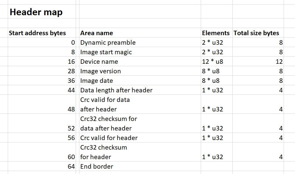
Lets explain a bit the parts.
Dynamic preamble
Actually just a cooler name for somewhat mundane thing. Remember the Cortex-M4 vector table:
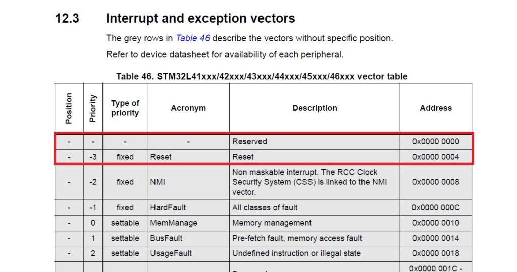
The first 4 bytes is the stack address, the next 4 bytes is address of the reset handler routine which set-ups the system.
Our trick here is to use these 8 first bytes from the vector table as the first bytes of the header. This way the header is also executable from the start!
Image start magic
This is by our choosing 2 * u32 somewhat unique values. I chose 0x461C0000 and 0x12345678. Why are these handy? We could want in bootloader to scan the flash for these identifiers dynamically and try to boot based on the found information. The bootloader would verify the crc checksums, then set stack pointer and program counter to the values 8 bytes and 4 bytes before magic, respectively. The code execution would continue from reset handler of the image.
Device name
Name of the device, so we can easily tell what device this image can run on.
Image version
Obviously, version of the SW on the image is quite helpful, for example if we are doing software upgrade.
Image date
Date of image to get approximate idea about how new it is.
Data length after header (placeholder)
This is very important number. We have dedicated the header to be always 64 bytes. But the length of the firmware image can vary. The length will be here, but initially it is zero. We need to fill info in later via tool.
We could, in theory, also use dynamic symbols and linker magic to populate this variable during compile-time, but I have not tested it. And I think that it is somewhat more straightforward to let the tool fill it in in thorough analysis afterwards.
Crc valid for data after header (placeholder)
Flag saying if crc32 has been calculated for the “actual data” after header. Initially zero.
Crc32 checksum for data after header (placeholder)
The crc32 checksum for the “actual data” after header. Initially zero.
Crc valid for header (placeholder)
Second crc flag. This tells if the crc32 checksum guarding the header is valid/calculated. Initially zero.
Crc32 checksum for header (placeholder)
Final part of the header. Crc32 checksum up to this position from start of header. So in other words, calculated from header bytes 0-60 and result put to bytes 60-64. Initially zero.
A question may now arise: Why use crc32 here? Indeed, for example crc16 could be just fine. But we need to implement crc32 algorithm anyways, so we can as well use it for header also.
General note: It is highly advised to make the sizes of all parts of the header dividable by 4.
Linker script modifications
We need a bit of linker magic to get going. We redefine from the beginning of SECTIONS things like this:
/* Sections */
SECTIONS
{
.image_header_begin :
{
. = ALIGN(4);
KEEP(*(.image_header_begin))
KEEP(*(.image_header_begin*))
} >FLASH
.image_header_body :
{
KEEP(*(.image_header_body))
KEEP(*(.image_header_body*))
} >FLASH
.isr_vector :
{
/* Isr vectors need to be 512 byte aligned
We could save flash data if we put this to
ram, but for simplicity we leave it as it is.
*/
. = ALIGN(512);
KEEP(*(.isr_vector)) /* Startup code */
. = ALIGN(4);
} >FLASH
Here are explanations of additions:
.image_header_begin
In the very beginning of flash, we create .image_header_begin section, to explicitly force the stack and reset handler address there. This is what we called “dynamic preamble”. See that we align this only from beginning and to 4 byte border. But of course it is normally there already.
Especially note that we don’t align it from the end.
.image_header_body
The rest of the header (64 – 2 * 4 = 56 bytes). No alignment in the beginning, because we want to stack it together with .image_header_begin .
.isr_vector
The interrupt vector table. Compared to “normal”, there is one significant addition. It is alignment on the 512 byte border. Why? Take a look at the programming manual:
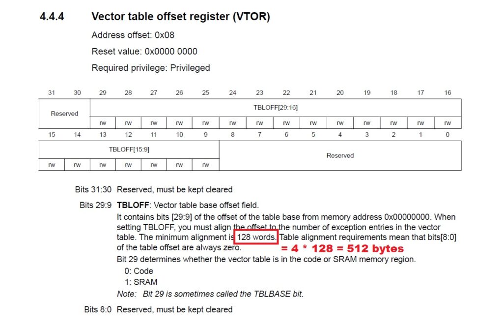
So in other words (heh), the vector table needs to be always aligned to 512 bytes. Otherwise interrupts crash the system. Trust me, I tried. This is why we have ALIGN(512) in the linker script. (I actually wonder why ALIGN(512) is not the default always.)
Now there is a tiny drawback. Because of the alignment, there is a gap in the flash from the end of our header (offset 64 bytes) to the beginning of the actual interrupt vector table (offset 512 bytes). If you want, you can manipulate the linker script to put more sections in the gap to reduce empty space. Or you could even copy the interrupt vector table to memory manually and point it via VTOR. But to keep things simple, we will just have the gap for now.
Startup code modifications
We need some startup code modifications to make things work.
startup_stm32l432kcux.s
In the startup assembly file startup_stm32l432kcux.s we define this new identifier:
.syntax unified
.cpu cortex-m4
.fpu softvfp
.thumb
.global g_headerBegin
.global g_pfnVectors
.global Default_Handler
/* start address for the initialization values of the .data section.
defined in linker script */
.word _sidata
And further down, we define contents:
Infinite_Loop:
b Infinite_Loop
.size Default_Handler, .-Default_Handler
/**
* @brief Image header begin data to make it runnable as is.
*/
.section .image_header_begin,”a”,%progbits
.type g_headerBegin, %object
.size g_headerBegin, .-g_headerBegin
g_headerBegin:
.word _estack
.word Reset_Handler
/******************************************************************************
*
* The minimal vector table for a Cortex-M4. Note that the proper constructs
* must be placed on this to ensure that it ends up at physical address
* 0x0000.0000.
*
******************************************************************************/
.section .isr_vector,”a”,%progbits
See what we did there? We copied how the first 2 * u32 words are in the actual interrupt vector table (stack address and reset handler address). We are also pushing it to our .image_header_begin section we defined in the linker file.
system_stm32l4xx.c
Lets take a look at system_stm32l4xx.c . This file is called from the startup assembly, specifically the function SystemInit(). It needs modifications:
void SystemInit(void)
{
SCB->VTOR = 0x8000200;
__DMB();
#if defined(USER_VECT_TAB_ADDRESS)
/* Configure the Vector Table location ————————————-*/
SCB->VTOR = VECT_TAB_BASE_ADDRESS | VECT_TAB_OFFSET;
#endif
/* FPU settings ————————————————————*/
#if (__FPU_PRESENT == 1) && (__FPU_USED == 1)
SCB->CPACR |= ((3UL << 20U)|(3UL << 22U)); /* set CP10 and CP11 Full Access */
#endif
So what we did, we set the vector table address to the special VTOR register. (Btw. this register is not available on Cortex-M0, might be available on some models on M0+ they say.)
Remember we defined in linker script the interrupt vector table to be aligned to 512 bytes, basically 512 bytes from flash start? See the 0x200 in the address (0x8000200)? 0x200 = 512 dec. So, here we are basically telling to the processor “Hey, you know, interrupt vector table actually begins from first 512 byte offset, bro.”
After our VTOR stuff we issued __DMB() or data memory barrier call, which is always a good thing after changing VTOR. (Best explained in this Cortex-M33 document.)
After this we deleted redundant VTOR code coming from STM32 so it does not by accident mess up anything.
Populating header data and placeholders in program code
We need to place the header data we already know somewhere. So a file should do that. I created image_info.c which is basically as this:
#include “image_info.h”
#include <stdint.h>
// Header area size = 64
// Offset 0
// Dynamic preamble (stack and reset handler addresses): 2 * 4 bytes
// Offset 0 + 8
const uint32_t gcau32ImageStartMagic[2] __attribute__ ((section (“.image_header_body”))) = {0x461C0000, 0x12345678 };
// Offset 8 + 8 = 16
const uint8_t gcau8DeviceName[12] __attribute__ ((section (“.image_header_body”))) =
{‘N’, ‘u’, ‘c’, ‘l’, ‘e’, ‘o’, ‘L’, ‘4’, ‘3’, ‘2’, ‘K’, ‘C’ };
// Offset 16 + 12 = 28
const uint8_t gcau8ImageVersion[8] __attribute__ ((section (“.image_header_body”))) =
{‘v’, ‘.’, ‘1’, ‘.’, ‘2’, ‘.’, ‘7’, 0};
// Offset 28 + 8 = 36
const uint8_t gcau8ImageDate[8] __attribute__ ((section (“.image_header_body”))) =
{‘2’, ‘0’, ‘2’, ‘1’, ‘0’, ‘8’, ‘1’, ‘7’};
// Offset 36 + 8 = 44
const uint32_t gcu32AfterHeaderDataLength __attribute__ ((section (“.image_header_body”))) = 0;
// Offset 44 + 4 = 48
const uint32_t gcu32AfterHeaderDataCrcValid __attribute__ ((section (“.image_header_body”))) = 0;
// Offset 48 + 4 = 52
const uint32_t gcu32AfterHeaderDataCrc32 __attribute__ ((section (“.image_header_body”))) = 0;
// Offset 52 + 4 = 56
const uint32_t gcu32HeaderCrcValid __attribute__ ((section (“.image_header_body”))) = 0;
// Offset 56 + 4 = 60
const uint32_t gcu32HeaderCrc32 __attribute__ ((section (“.image_header_body”))) = 0;
// Offset 60 + 4 = 64
This is very self explanatory. We populate the fields of the header we know at this point. We know the magics, device name, image version and image date. Anything else we don’t know, so we set it to zero.
We also force everything to our section .image_header_body .
Compiling and disassembling gets us this:
L432KC-dynamic-header.elf: file format elf32-littlearm


Disassembly of section .image_header_begin:

08000000 <g_headerBegin>:
8000000: 20010000 andcs r0, r1, r0
8000004: 08000691 stmdaeq r0, {r0, r4, r7, r9, sl}

Disassembly of section .image_header_body:

08000008 <gcau32ImageStartMagic>:
8000008: 461c0000 ldrmi r0, [ip], -r0
800000c: 12345678 eorsne r5, r4, #120, 12 ; 0x7800000

08000010 <gcau8DeviceName>:
8000010: 6c63754e cfstr64vs mvdx7, [r3], #-312 ; 0xfffffec8
8000014: 344c6f65 strbcc r6, [ip], #-3941 ; 0xfffff09b
8000018: 434b3233 movtmi r3, #45619 ; 0xb233

0800001c <gcau8ImageVersion>:
800001c: 2e312e76 mrccs 14, 1, r2, cr1, cr6, {3}
8000020: 00372e32 eorseq r2, r7, r2, lsr lr

08000024 <gcau8ImageDate>:
8000024: 31323032 teqcc r2, r2, lsr r0
8000028: 37313830 ; <UNDEFINED> instruction: 0x37313830

0800002c <gcu32AfterHeaderDataLength>:
800002c: 00000000 andeq r0, r0, r0

08000030 <gcu32AfterHeaderDataCrcValid>:
8000030: 00000000 andeq r0, r0, r0

08000034 <gcu32AfterHeaderDataCrc32>:
8000034: 00000000 andeq r0, r0, r0

08000038 <gcu32HeaderCrcValid>:
8000038: 00000000 andeq r0, r0, r0

0800003c <gcu32HeaderCrc32>:
800003c: 00000000 andeq r0, r0, r0

Disassembly of section .isr_vector:

08000040 <g_pfnVectors-0x1c0>:
...

08000200 <g_pfnVectors>:
8000200: 20010000 andcs r0, r1, r0
8000204: 08000691 stmdaeq r0, {r0, r4, r7, r9, sl}
8000208: 080005c9 stmdaeq r0, {r0, r3, r6, r7, r8, sl}
Another general piece of info: There will be discrepancies about how the data is in the dissassembly and in the binary file, because of endian handling. Hex editor tells the final truth.
So as we can see, the header is now in the beginning, it has the same beginning as the actual interrupt vector table, and all our information we put in the header body are there, but many still zero. Lets fix that next.
Putting rest of header data in automatically after build
The rest of the header data needs to be fixed. I wrote a program for that, check CrcTool. (Btw .exe is provided, but I compile it with TDM-GCC-64 from https://jmeubank.github.io/tdm-gcc/download/ , my package is tdm64-gcc-10.3.0-2.exe, aka 64+32-bit MinGW-w64 edition).
The executable runs through the binary, it does the following:
- Checks the actual size of the data after header, puts it in place
- Calculates the crc32 of the data after header
- Puts in place flag that crc for data after header is correct, also puts in place the crc32 for data after header
- Puts in place the flag that header crc is correct
- Now that everything else is in place, calculates the crc32 of the header data and places the checksum at the last 4 bytes of the header.
But how to run the executable always after build? We just add it as post-build step:
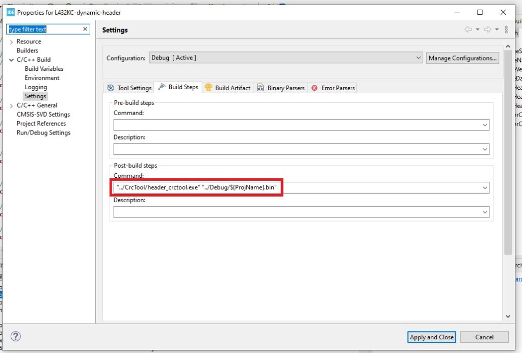
Verbatim syntax is:
"../CrcTool/header_crctool.exe" "../Debug/${ProjName}.bin"
Btw don’t worry if the tool fails for real reason, it emits error code and the build is signaled failed at that point.
Example output of the tool file:
"../CrcTool/header_crctool.exe" "../Debug/L432KC-dynamic-header.bin"
Opening file ../Debug/L432KC-dynamic-header.bin
Found dynamic preamble: 0x20010000 0x08000691
Found MATCHING header magic values: 0x461C0000 0x12345678
Device name: NucleoL432KC
Image version: v.1.2.7
Image date: 20210817
After header data length: 6712
Added after header data crc32: 0x9A2E3059
Added header data crc32: 0x9957D9CB
Writing to ../Debug/L432KC-dynamic-header.with_crc32.bin
Successfully wrote file with correct header to ../Debug/L432KC-dynamic-header.with_crc32.bin
Verification that it works
Header structure
To verify that our thing works, we first validate the header structure. It is best to go to a Linux system / subsystem and transfer both binaries there for hexdumping:
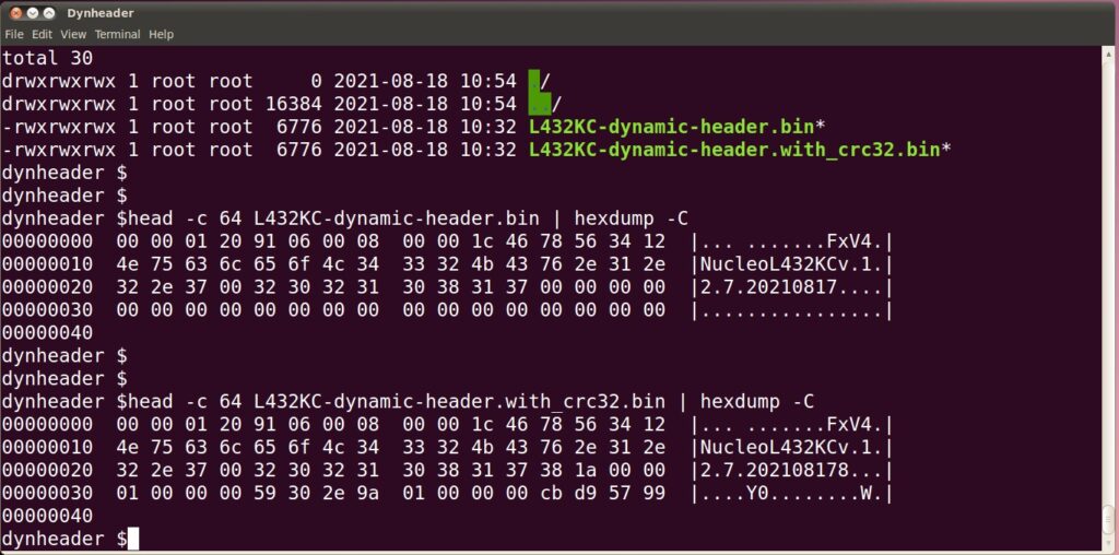
Now your question is, why the hell stack address is 0x00000120? But no, it is not. We are just looking at little endian data. So it is actually reversed. If we reverse it is 0x20010000. Makes more sense, right? Also the reset handler table address 0x91060008 reversed byte-by-byte 0x80000691 . Good.
Next question is, why we see cleartext “NucleoL432KC” in the dump? Well, because it is not u32. It is a byte array of u8:s basically. They align naturally in the “right” order.
Alright. If actually comparing the dumps, we can see that initial file has all the crc-related fields zeroed, as it should be. And the binary which has been trough the crctool, it has all those fields set.
From the “operated” binary our header claims:
- Data lenght after header = 0x381a0000 reversed = 0x00001A38 = 6712 dec bytes
- Crc valid for data after header = 0x01000000 reversed = 0x00000001
- Actual crc32 of data after header = 0x59302e9a reversed = 0x9A2E3059
- Crc valid for header = 0x01000000 reversed = 0x00000001
- Actual crc32 of the header (from byte 0 to byte 60) = 0xcbd95799 reversed = 0x9957D9CB
Lets see if this checks out. Extracting after header data from original binary and checksumming it:
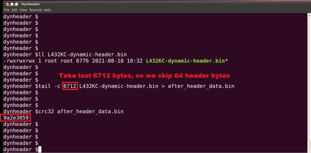
We can see that the full size of binary is 6776 bytes. If we subtract 64 header bytes, we get 6712. This is exactly what the header said.
Also, the crc32 for after data header data is 0x9A2E3059 , so exactly the match from header.
Then lets take the header checksum. Lets take final header data from byte 0 to byte 60 and checksum it:
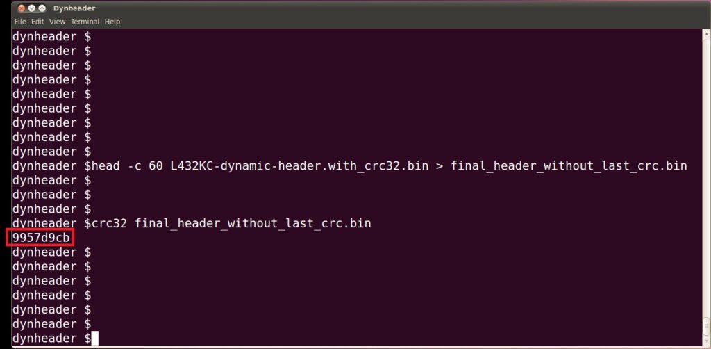
Crc32 is 0x9957D9CB. Guess what. Just what our header told us! Header is 100% valid.
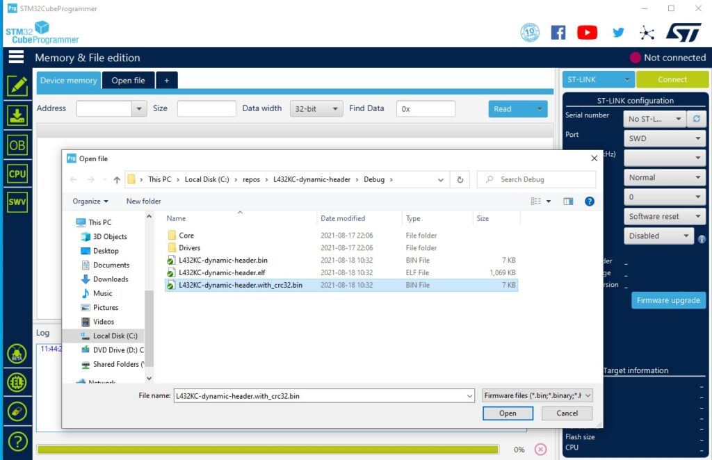
Debugger
Lets finally see things in debugger. We need to first flash the binary manually to target. I’m using STM32CubeProgrammer:
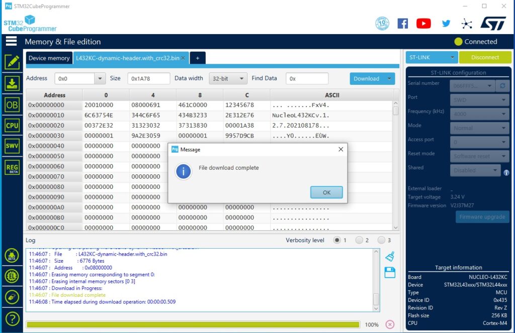
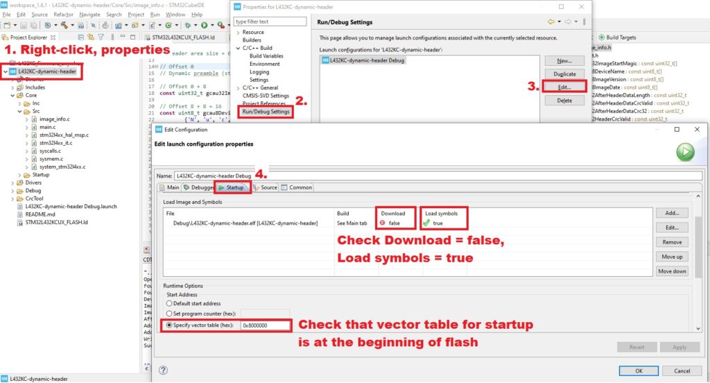
Then to STM32CubeIDE. Set in launch options to only load symbols, NOT TO DOWNLOAD:
Lets start debugger, pause it and finally observe values:
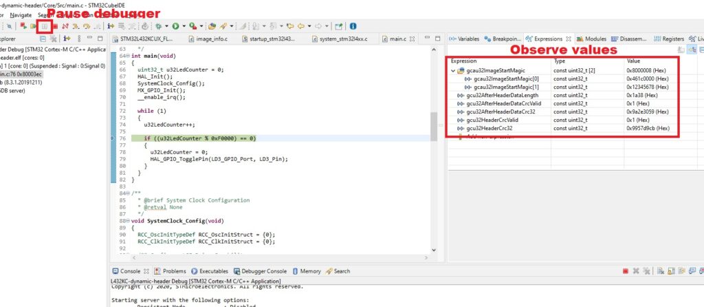
gcau32ImageStartMagic const uint32_t [2]   0x8000008 (Hex)
  gcau32ImageStartMagic[0] const uint32_t  0x461c0000 (Hex)
  gcau32ImageStartMagic[1] const uint32_t  0x12345678 (Hex)
gcu32AfterHeaderDataLength const uint32_t  0x1a38 (Hex)
gcu32AfterHeaderDataCrcValid const uint32_t  0x1 (Hex)
gcu32AfterHeaderDataCrc32 const uint32_t  0x9a2e3059 (Hex)
gcu32HeaderCrcValid const uint32_t  0x1 (Hex)
gcu32HeaderCrc32 const uint32_t  0x9957d9cb (Hex)
This is just great, the values are just exactly we wished! The code is using using exactly the values we changed with crctool.
Closing words
With the methods shown earlier we can build a dynamically generating program header. It can be used in external and internal validation and it is extremely handy in firmware upgrade situations. There is no more gluing an artificial header to the binary, you can just start executing code from the beginning of the header!
Naturally everything can be improved and done better. What was shown here was proof of concept. Did you like it? Do you have proposed modifications? Drop a line in the comments.
The actual code is here: https://github.com/usvi/L432KC-dynamic-header .