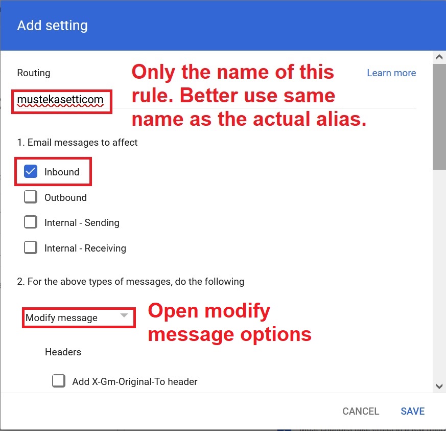
With today’s rampart email address harvesting, it is considered a good policy to use a custom email address for every given service. If you have Google Workspace with Admin privileges, there is the possibility to use the aliases functionality. But after you have run out of the allowed number of aliases, you can still add more via routing. Lets see how. Continue reading “Creating custom email aliases in Google Workspace Admin using routing (2024)”
IT System Design 101: Decoupling of address and entity data in a self-addressing bus
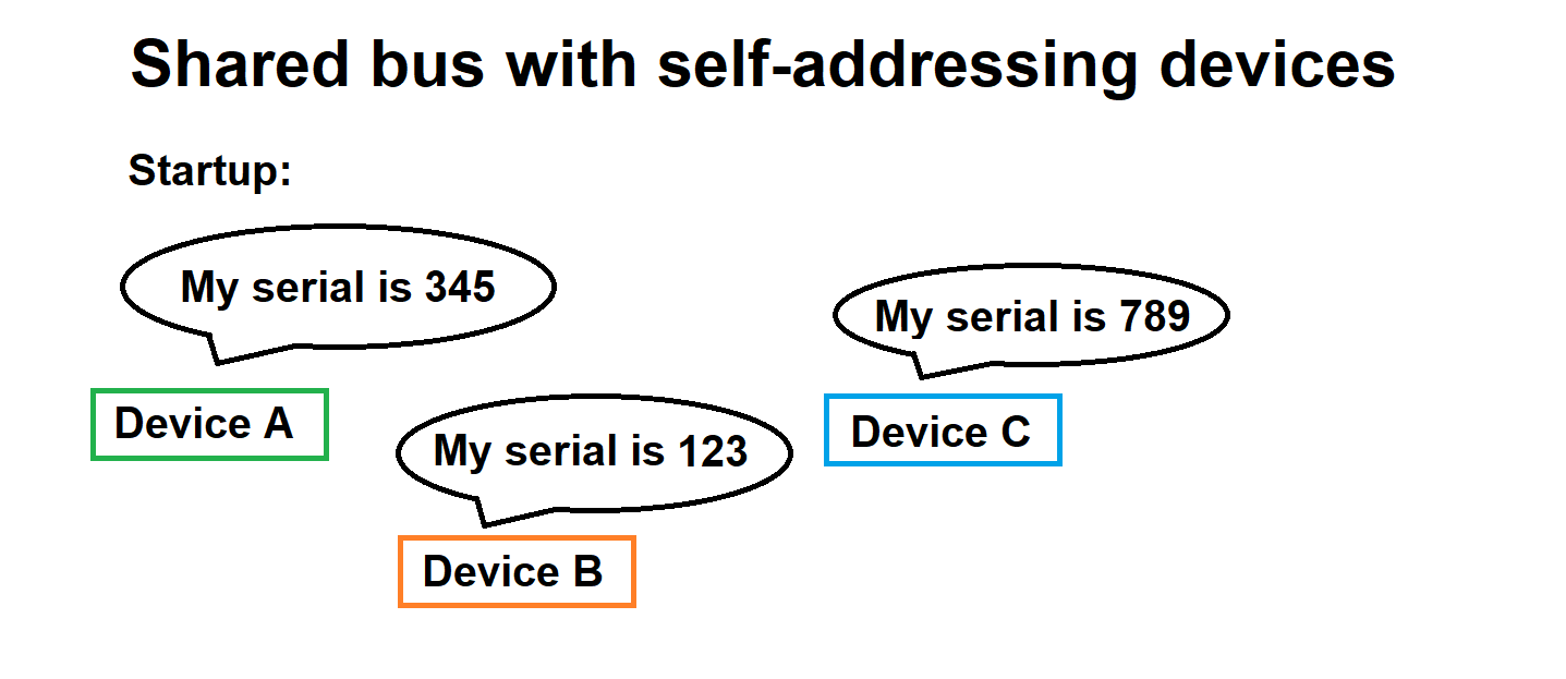
There exists a special use-case for data handling in a situation where multiple self-addressing devices are using the same bus for communication. In the common case self-addressing devices work as follows:
- Each device has hardcoded unique piece of information to be used as a seed value for addressing (lets call this “serial number” for simplicity)
- Upon powering up, the devices negotiate with each other, either on the common bus (think application CanBUS) or nondocumented/out-of-band means
- During the negotiations, the devices agree about bus addresses of each device, based on presence of each device and everyone’s serial
IT System Design 101: Design for Deltas
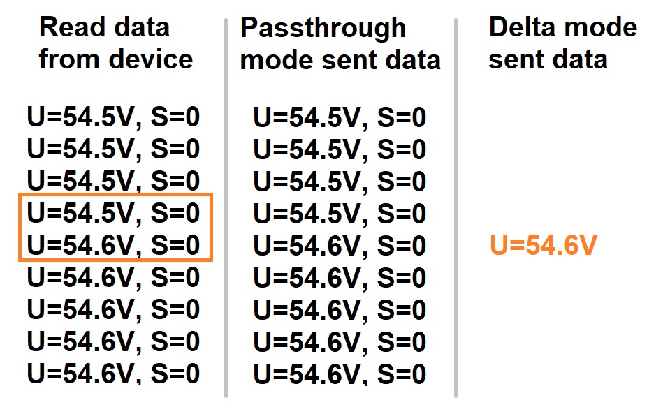
In the previous article about system design I briefly hinted about a beneficial byproduct of correctly partitioned subsystems and well-defined APIs. For the lack of a better expression, I call this property “delta capability” or “delta mode”. What does it mean? It means that we communicate only the data changes the subsystem sees. Let’s formulate an example.
IT System Design 101: Subsystems are NOT just dumb pipes
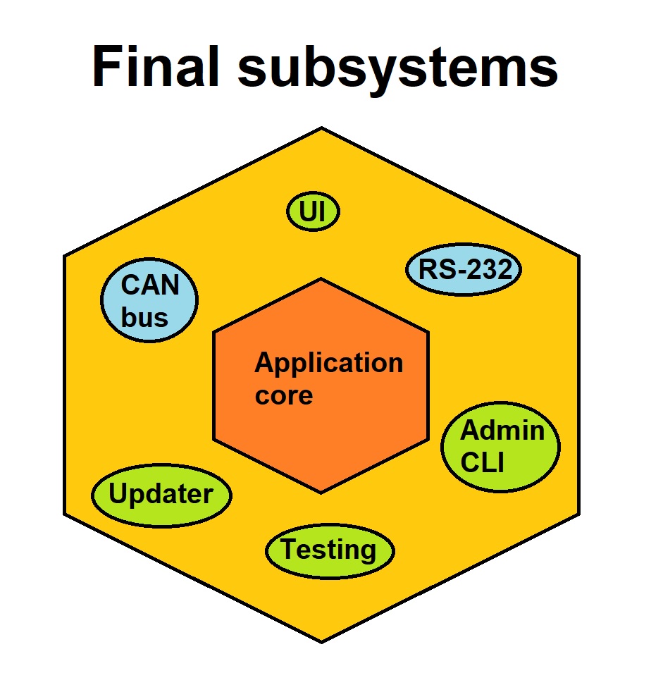
One design pattern in non-trivial IT systems is as follows. There exists a central authority of data and business logic with subsystems interfacing it. This, contemporarily somewhat obvious model, is called the Hexagonal Architecture and was first formalized in writing by Alistair Cockburn in 2005 (see https://en.wikipedia.org/wiki/Hexagonal_architecture_(software) ).
What is a subsystem in our context then? It is a system managing a domain (“a collection of things”), communicating to the central authority with a well-defined API. As with everything else, subsystems can be defined and implemented in different ways. One bad way to implement subsystem is to treat it as just a dumb pipe just passing data around. I will explain my rationale.
Continue reading “IT System Design 101: Subsystems are NOT just dumb pipes”
IT System Design 101: Nothing is as prevalent as temporary mock or debug program
I believe the following happens to every seasoned software engineer during some part of their career. You have been tasked to create a new program. Or you just start to create it yourself to assist you in some time-consuming mundane tasks. You pay no attention to code quality. It is enough that it just works. So, you cut some corners. Maybe there is a new library you are trying. You fiddle around with the parameters, stick in 1, 0, NULL in some obscure order until it works. You leave in the code a lot of magics (pure numbers and symbols which do not tell WHY they have been defined as such). Because, you know, it is just a temporary debug program.
What happens in reality, at an alarming rate, is that these programs, meant strictly temporary, become actually quite permanent. In many cases they end up outliving the contract periods of the engineer originally writing them.
Continue reading “IT System Design 101: Nothing is as prevalent as temporary mock or debug program”
IT System Design 101: Introduction
During the past few decades, I have been involved in multiple embedded IT systems in distinct roles. I have been developing, maintaining, and designing. I have worked with individual subcomponents and with complete systems. I have seen ready-made stuff, implemented some myself and see others create new in parallel.
Many times, the result has been somewhat working. Many times, however, sub-optimality has been involved in some way. Part of the blame falls on me and part on other people. I am in no position to hold anyone else responsible for the problematic stuff than myself. And to be honest it has been many times a great learning experience to work out all the kinks out there and challenge previous thinking about the state of things.
IT System Design 101 will be a series of articles I will be writing about how to design an IT system. Emphasis will be on systems with embedded actors. There is no guarantee that the design patterns I’m going to lay down will result in a perfect system. I am quite sure though that the result will not be the worst possible.
Below will be an updating table of contents about already written and upcoming articles.
IT System Design 101: Nothing is as prevalent as temporary mock or debug program
IT System Design 101: Subsystems are NOT just dumb pipes
IT System Design 101: Design for Deltas
IT System Design 101: Decoupling of address and entity data in a self-addressing bus
Orange Pi Zero 2W at first glance
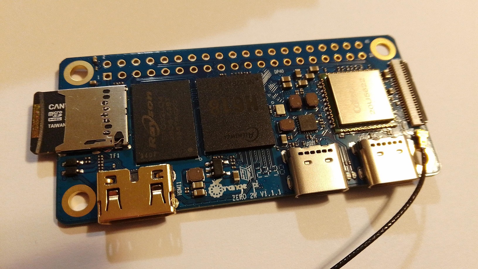
Orange Pi has recently introduced the Orange Pi Zero 2W single-board computers. There are a couple of variants, with changing amount of RAM, maxing at 4 GB. The CPU is a 4 core Allwinner H618 Cortex-A53. The main board houses CPU, some system chips, antenna connector, micro-SD socket and 16 MB flash. There is also mini-HDMI socket as well as 2 USB-C sockets, one for power in and one for general peripherals. There is also handy 2 x 20 pin hole grid in the main board, and thank heavens they have not soldered the provided pin header in because it would actually more than double the height of the construction. They played this very smart. This does not happen often in electronics industry.
One side of the main board has a flat cable connection possibility to external daughter card housing IR receiver, RJ45 Ethernet, some buttons, 2 regular USB ports and audio jack. The board is incredibly thin. Everything in this design hints it will be a killer app for so-called “smart” TVs.
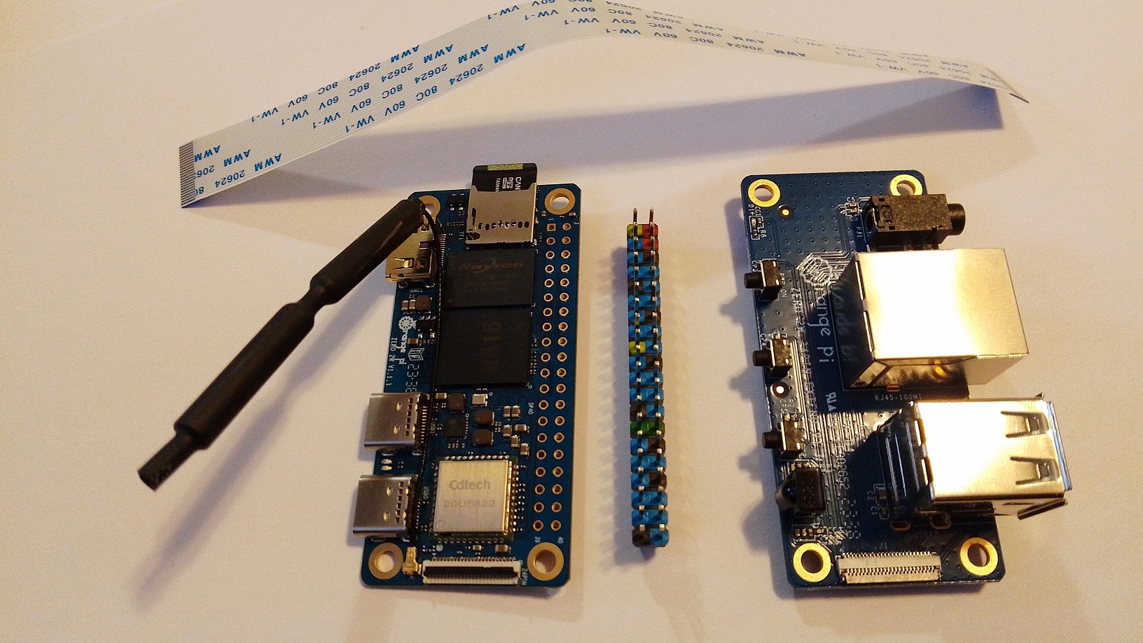
We took a short exploration tour of the product tour with the vendor-provided Debian Linux (Note: Daughter card was NOT connected nor tested.) Read more below.
Epoll tutorial and understanding the overlooked epoll_data_t
Epoll is a mechanism of Linux Kernel / Linux C runtime to monitor multiple file descriptors for I/O. Lets say you have a server program which has open connections as file descriptors. Epoll mechanism offers more performant “watching” of all these file descriptors for activity compared to some other options, like select(). Some tutorials about epoll exist on the internet, but many fail to acknowledge WHY what is happening is actually happening. So allow me to walk you through with this small example program utilizing epoll.
Continue reading “Epoll tutorial and understanding the overlooked epoll_data_t”
Forcing VMware virtual machines to appear 32-bit on 64-bit hosts
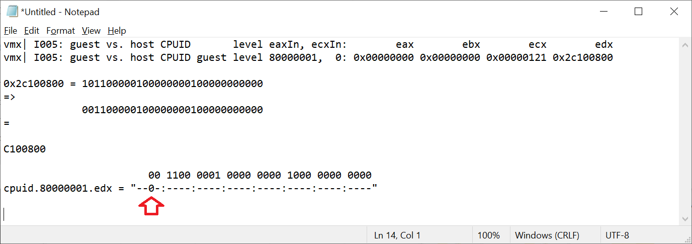
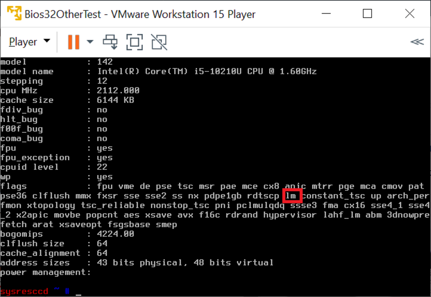
There are sometimes needs to run 32-bit VMware guest images on a 64-bit host. This is possible, for example in VMware Workstation 15 Player. The out-of-the-box behavior, however, is that the Player passes trough the CPU information more or less as such. The result is that the guest sees a x86_64 processor, not a x86 processor. Frequently this detection is made by reading the CPUID 29th feature bit for so-called “long mode” (see: https://en.wikipedia.org/wiki/CPUID#EAX=80000001h:_Extended_Processor_Info_and_Feature_Bits ). As this is seen by the guest, it might think it needs to run 64-bit image (Player does not force this, it is a decision of the image itself). The long mode bit seen from Linux /proc/cpuinfo :
Continue reading “Forcing VMware virtual machines to appear 32-bit on 64-bit hosts”
Portable Position-Independent Code (PIC) bootloader and firmware for ARM Cortex-M0 and Cortex-M4
Disclaimer 2024-05-07
Although PIC was a very interesting trek in the deep embedded territory, I’m not that confident about the benefits as of today, 2024-05-07. See the comment below from “manne”. He discovered that even though some aspects of my solution works, it is basically unusable in the comprehensive scale. Therefore, for the time being, I am discouraging people from using PIC in real-world applications, and only exploring the subject for academic interest. I will write later more in-depth analysis of shortcomings and will also propose some compiler changes to tackle the main issue and also some some generic PIC optimizations.
Rest of the text is kept for posterity.
How to implement Position-Independent Code for microcontroller (MCUs) is a question which has been asked countless and countless of times all over the Internet. The answers and “solutions” are usually whippersnappering comments dropping a couple of key terms they probably just googled up without any kind of intrinsic knowledge about how the system should be working.
Sometimes the answer is “OK I got it working” followed by eternal silence from people asking clarifications. In other words, it looks like the task is very difficult and once people get it to work, it is so valuable they want to hide the details. In a way I cannot blame them much; it took me 6 months of half-time work every now and then to understand everything.
So, some 6 months ago I set myself a goal: “Create a portable solution where an intelligent bootloader can boot firmware images from any address in flash on Cortex-M0 or Cortex-M4 platform.” Finally, as of today 2022-01-16, I consider I have solved the problem in an intelligent and understandable way.
Funnily, I think I am the only person on planet Earth who has made available readily working example code and documented the code in a way I am doing now in this post.
Those impatient can explore the fully working STM32CubeIde codes at GitHub, for Cortex-M0: https://github.com/usvi/F070RB-BL-FW and for Cortex-M4: https://github.com/usvi/L432KC-BL-FW . (One might ask why one would use this kind of bloated stock configuration for developing on MCUs. Believe me, I’m doing it here only for pedagogical reasons. This way it is easier for noobs having the needed evaluation boards to verify that the code is working.)
The set of code I have created is a proof-of-concept, working for the C language. There might, and I underline, might be unforeseen problems when amount of global variable gets absurdly high. In any case, comments and criticism is more than welcome.
If you are ready to dive into the deep end of Cortex-M boot process, PIC constructs, esoteric debugging and linker script optimizations, continue reading…
