Recently I described my friend that I was working with Position-Independent Code on a Cortex-M0 and Cortex-M4 environment. To my surprise, he was more interested about “why” and not “how”. I think before revealing the nitty-gritty details of this domain, I can give readers an overview about things.
What is Position-Independent Code (PIC) on ARM Cortex-M MCU environment?
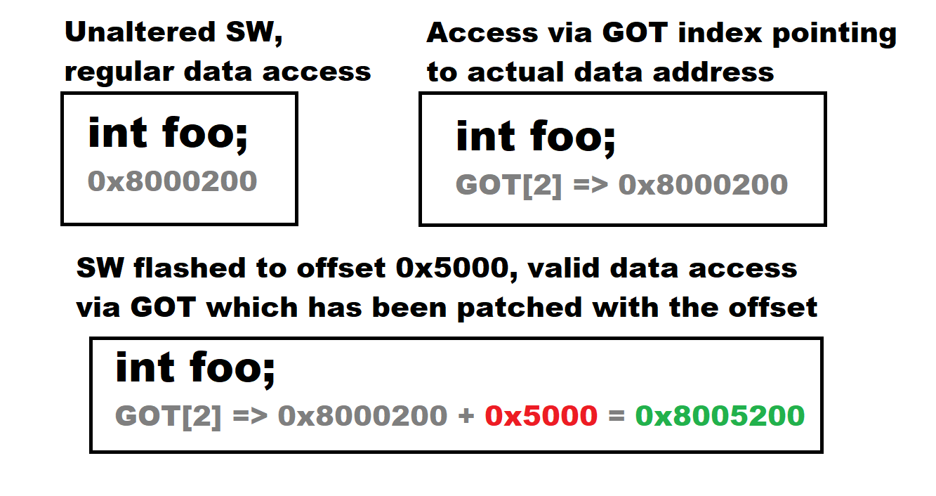
When one creates for example a simple LED flicking program for Cortex-M MCU, it normally starts from the first flash memory position 0x8000000. What happens if you use default setting but flash the same image a bit further, for example to 0x8005000? The poor software would still try to access vital bits from 0x8000xxx, encounter garbage and crash.
How to fix this? There is a technique called Position-Independent Code, or PIC that can be utilized. PIC is basically and normally a set of C compiler options which creates a centralized structure for accounting global resources, especially global variables. Depending on the options, we can organize the structure so that every global variable reference is reference via this global resource, which is called Global Offset Table, or GOT. Every reference is done by referencing the actual variables via GOT table using indexes. Compiler handles this automatically.
It turns out that with proper manipulation GOT can help us when we run the 0x8000000 firmware from 0x8005000. How? We will get back to this in a later post. But now it suffices to say that when the SW image runs from 0x8005000, we can eventually patch all the addresses in the table with the distance 0x5000 and make things work. The picture below possibly helps to illustrate the situation.
Another corollary requirement is managing the interrupt vector table in a similar fashion, but we will discuss it also in more detail in a later post.
Why would we need PIC-based software on ARM Cortex-M MCU environment?
Back to my friend. He postulated that some people, including himself, would be much more interested about why we need to do what we are now doing. And I cannot really blame him. He presented valid notions about possible shortcomings and points of failure in the GOT-driven system.
The root cause for all this hassle was a system I was tasked to investigate. The system was eventually a management system which manages other, MCU-based devices. The management system also can perform a firmware update on the managed devices. Other requirements were that the allowed downtime of an individual device during firmware upgrade was less than one second and that the device should be able to recover from a failed firmware upgrade. Final requirement was that the storage space on the management system was very limited and thus as little space as possible was available for firmware upgrade images.
So, the constraints in list form were:
- A central management device needs to make firmware upgrades on node devices
- The allowed individual node downtime from normal operations during firmware upgrade is very little (less than one second)
- The node should be able to recover from a bad firmware upgrade (for example a flipped bit in transit)
- The storage space for node firmware upgrade image is very limited
How to attack this problem set?
First requirement can be considered that the firmware on a node is at all upgradeable. In this setting a communications bus is needed and there should be functionality handling transfer of the firmware data from the management system.
Near-zero downtime requirement basically means that we just cannot take the otherwise functioning node and put it to a special firmware upgrade mode where at the same time the normal operations are disrupted. This means that there needs to be dual-bank system where one firmware image is running while the space of the non-running bank is filled with firmware update data little by little while retaining normal operations. This requirement also hints about necessity of having a dedicated, immutable bootloader.
The ability to recover from a bad firmware upgrade is a dead giveaway about having dedicated bootloader at the beginning of the flash. Bootloader checks a header from the firmware image beginning and extracts a checksum. This checksum is compared with firmware data contents. Failing checksum triggers using earlier firmware again.
Combined with previous requirements we now have a system with a dedicated bootloader selecting and validating either firmware bank 1 or firmware bank 2 during boot in a fast fashion.
Finally, is the requirement and issue with the storage space. In a “normal” setting we would compile 2 individual firmware images. The functionalities of both images would be the same, the only difference being that the internal reference addresses. So it could be that bank 1 firmware references a variable from flash address 0x8005200 where the same variable is referenced by bank 2 firmware from address 0x8010200.
In order to save space and the only way to satisfy all other constraints is to use a solution where the same firmware image can run either from bank 1 or from bank 2. This is where the PIC solution comes into play, allowing the same image run (with minimal constraints) from anywhere in the flash if it is slightly helped by a bootloader.
The reasoning above sent me exploring the minute details of ARM Cortex-M0 and Cortex-M4 boot process and esoteric compiler and linker script options. But more of this in the next post.
Appreciate this program,I ‘m blocked at ‘bl main’ in start.s.Symbol main is offered but here jump to the absolute main addr in startup.s, how to deal with it?
/*Call the main function */
bl main
800cc60: f7fe fd48 bl 800b6f4
Can you describe more of the situation. Is this my code or yours?