Disclaimer 2024-05-07
Although PIC was a very interesting trek in the deep embedded territory, I’m not that confident about the benefits as of today, 2024-05-07. See the comment below from “manne”. He discovered that even though some aspects of my solution works, it is basically unusable in the comprehensive scale. Therefore, for the time being, I am discouraging people from using PIC in real-world applications, and only exploring the subject for academic interest. I will write later more in-depth analysis of shortcomings and will also propose some compiler changes to tackle the main issue and also some some generic PIC optimizations.
Rest of the text is kept for posterity.
How to implement Position-Independent Code for microcontroller (MCUs) is a question which has been asked countless and countless of times all over the Internet. The answers and “solutions” are usually whippersnappering comments dropping a couple of key terms they probably just googled up without any kind of intrinsic knowledge about how the system should be working.
Sometimes the answer is “OK I got it working” followed by eternal silence from people asking clarifications. In other words, it looks like the task is very difficult and once people get it to work, it is so valuable they want to hide the details. In a way I cannot blame them much; it took me 6 months of half-time work every now and then to understand everything.
So, some 6 months ago I set myself a goal: “Create a portable solution where an intelligent bootloader can boot firmware images from any address in flash on Cortex-M0 or Cortex-M4 platform.” Finally, as of today 2022-01-16, I consider I have solved the problem in an intelligent and understandable way.
Funnily, I think I am the only person on planet Earth who has made available readily working example code and documented the code in a way I am doing now in this post.
Those impatient can explore the fully working STM32CubeIde codes at GitHub, for Cortex-M0: https://github.com/usvi/F070RB-BL-FW and for Cortex-M4: https://github.com/usvi/L432KC-BL-FW . (One might ask why one would use this kind of bloated stock configuration for developing on MCUs. Believe me, I’m doing it here only for pedagogical reasons. This way it is easier for noobs having the needed evaluation boards to verify that the code is working.)
The set of code I have created is a proof-of-concept, working for the C language. There might, and I underline, might be unforeseen problems when amount of global variable gets absurdly high. In any case, comments and criticism is more than welcome.
If you are ready to dive into the deep end of Cortex-M boot process, PIC constructs, esoteric debugging and linker script optimizations, continue reading…
Recapping and extending the concept of Position-Independent Code in a bootloader / firmware image context
In the previous post I told a primer what Position-Independent Code, or PIC is. I told also, why I needed it. For the needs, I basically wanted an unaltered, single firmware image to run from any (properly-aligned) flash address.
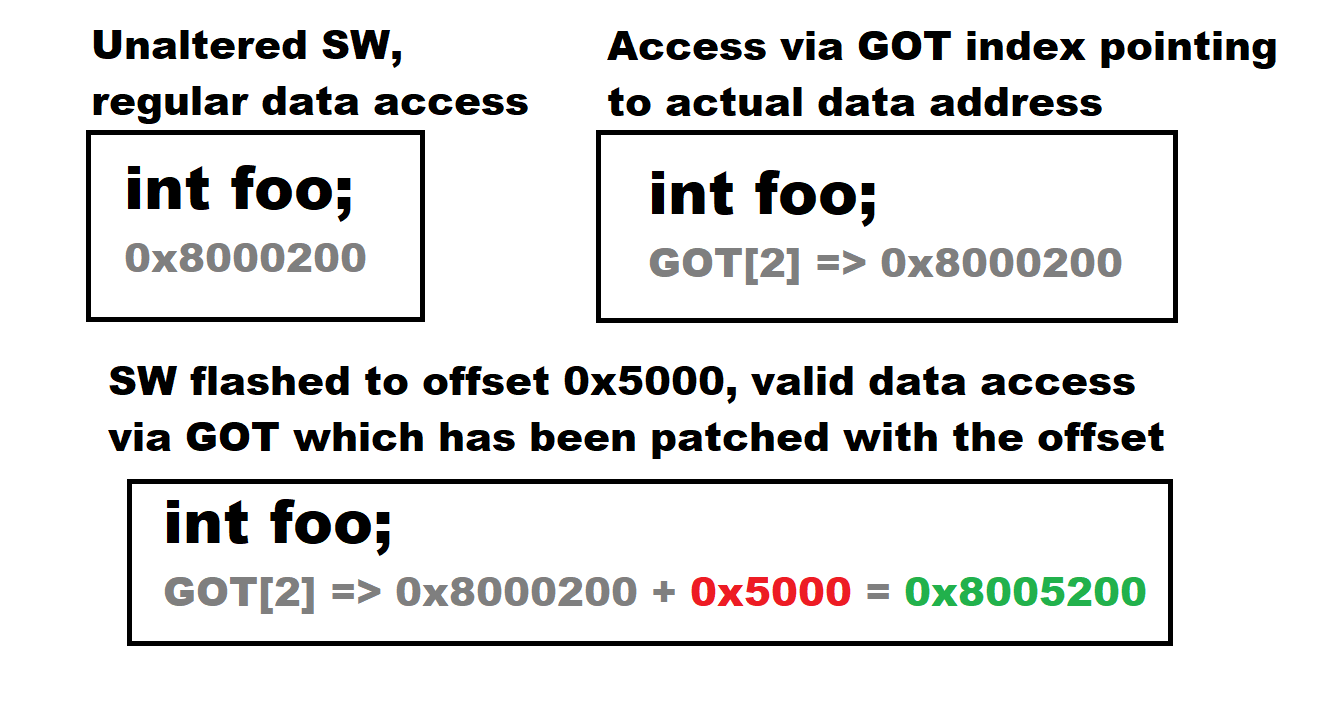
If you take a regular firmware image which expects to be for example in 0x8000000 flash address and put it to 0x8005000 and try to run it, it instantly bugs out. Why? Because the image has hard-coded addresses for data. If it wants to access data originally at 0x8000200, it gets garbage because data is now at 0x8005200.
PIC techniques are something that can alleviate this by creating an accounting mechanism called Global Offset Table, or GOT. When PIC software is run, it does not dereference memory locations by direct memory references. Instead, it references the GOT table indexes. It turns out if we manipulate the addresses from this table, we can have the PIC-enabled firmware to run from almost any address in flash. Situation is like in this picture:
In the earlier post I wrote: “PIC is basically and normally a set of C compiler options which creates a centralized structure for accounting global resources, especially global variables.” I also wrote that we need to do some operations to the interrupt vector table (ISR).
PIC, especially in a context where we have a bootloader and PIC-enabled firmware images, is more. It consists of these 4 core things:
- A bootloader which can “jump” to execute from an address from firmware flash area. (This address can be hard-coded, but you’ll see that I have implemented a system where the firmware image is sniffed out automatically from flash). This bootloader also passes some helpful data to the firmware image via registers. There is also verification checksum of the registers to determine if the firmware image is running bootloaded or standalone.
- Elegant linker script changes, especially in the PIC-enabled firmware image project. First, we need to add a dedicated location in beginning of RAM to store ISR table because many platforms expect the ISR table to be aligned at 512 bytes. A dedicated location for GOT is also needed to be defined. We need to also define some symbols about beginning and end locations of sections so we can bootstrap the system.
- A set of C compiler options to produce the GOT referencing convention we want, in this case referencing all global variables initially via indexes in the GOT table. These options are needed for C compiler only! Many sources fail to acknowledge this.
- A very precise and tedious assembly startup routines in the firmware image project. This assembly routine configures the firmware image addresses in a way that it can run from any address. And even standalone!
Lets go into details of all of these components and throw in omitted details as we go.
Bootloader
Bootloader is basically a software component which is immutable part of the system. Bootloader selects which firmware image is run and it also helps to run the image. Usual design constraints for a bootloader are:
- Takes as little space as possible.
- Does not use complicated stacks, peripherals or interrupts and tries to ensure everything possible is set to reset state.
- Has the ability to validate the available firmware images and boot the correct one.
Following these principles usually produces a bootloader small and simple enough to be thoroughly proofed and approved for production.
Lets look at our Cortex-M4 bootloader at https://github.com/usvi/L432KC-BL-FW/tree/master/L432KC_Bootloader_STM32CubeIDE . Lets start with the linker script https://github.com/usvi/L432KC-BL-FW/blob/master/L432KC_Bootloader_STM32CubeIDE/STM32L432KCUX_FLASH.ld . Vital excerpt follows:
MEMORY
{
RAM (xrw) : ORIGIN = 0x20000000, LENGTH = 64K
FLASH_BOOTLOADER (rx) : ORIGIN = 0x8000000, LENGTH = 20K
FLASH_FWAREA (rx) : ORIGIN = ORIGIN(FLASH_BOOTLOADER) + LENGTH(FLASH_BOOTLOADER), LENGTH = 256K - LENGTH(FLASH_BOOTLOADER)
}

__flash_bootloader_begin = ORIGIN(FLASH_BOOTLOADER) ;
__flash_fwarea_begin = ORIGIN(FLASH_FWAREA) ;
__flash_fwarea_end = ORIGIN(FLASH_FWAREA) + LENGTH(FLASH_FWAREA) ;
This configuration basically defines amount of RAM memory and flash partition into two areas; first a 20KiB bootloader area and 256KiB – 20KiB = 235KiB area for firmware. There are also symbol definitions so we can automatically export the vital address information.
Then lets inspect the actual code functionality, which is presented in a nutshell in the picture below:

Basically the only interesting code file is Core/Src/flash_scan_and_jump.c with two important functions. First function is vScanMainFirmwareFlashAddress() . This function starts to read the flash memory after the bootloader area. When it finds the first non-zero word (zero = 0xFFFFFFFF), it reports back this address via parameter. This address is the address of the beginning of the actual firmware image.
Another function is the jump function vDeInitAndJumpToMainFirmware(). It performs a couple of important tasks. The bootloader reads 2 words (2 x 4 bytes) from the firmware image beginning address. This information contains stack pointer address and reset handler address. Both are important but reset handler address is especially important.
The reset handler address points to a location of the Reset_Handler assembly routine of the firmware image. But there is a problem. The address we just read, it points to non-offsetted flash address. The address read might be for example 0x8000628. But the problem is that this address now points to the bootloader area. An offset is calculated from the firmware beginning address found earlier and bootloader start address. Lets say we found the firmware beginning address from 0x8005000. Then the offset would be 0x8005000 – 0x8000000 = 0x5000. This offset is added to the Reset_Handler address: 0x8000628 + 0x5000 = 0x8005628. Now we know what we need to start the firmware image by jumping to 0x8005628.
Last trick with addresses is checksum calculation. It is done by XORring firmware start address and firmware offset. This offset is later used to determine if firmware image is running autonomously or assisted by the bootloader. Picture description of the function up to this point follows:

Before jumping we need to do a couple of things more. First we need to check if this jump function has been given platform-specific de-initialization function as a parameter. That function needs to be executed to set as much functionality as possible to reset state.
The final parts of the function are inline assembly. We use dedicated machine registers to store the following data:
- r10 = Firmware address 0x8005000
- r11 = Firmware offset 0x5000
- r12 = Checksum 0x8000000
Finally we perform the jump by setting stack pointer value and branching to the real firmware Reset_Handler address 0x8005628. After this we say bye-bye to the bootloader.
Firmware linker script changes
Next we examine the firmware image linker script changes needed for the system to work. The file is available at https://github.com/usvi/L432KC-BL-FW/blob/master/L432KC_Firmware_anywhere_STM32CubeIDE/STM32L432KCUX_FLASH.ld . Lets take a look it piece-wise.
FLASH_FULL_LEN = 256K ;
RAM_FULL_LEN = 64K ;
RAM_ISR_LEN = 512 ;
This part defines some local variables we can use in defining the flash and ram memory structure. Doing it this way makes it easy to port different parts. This linker script is for Cortex-M4 with ISR vector size of 128 x 1-word (4 bytes) = 512 bytes.
MEMORY
{
  ISR_RAM (xrw) : ORIGIN = 0x20000000, LENGTH = RAM_ISR_LEN
  RAM     (xrw) : ORIGIN = ORIGIN(ISR_RAM) + LENGTH(ISR_RAM), LENGTH = RAM_FULL_LEN - LENGTH(ISR_RAM)
  FLASH    (rx) : ORIGIN = 0x8000000, LENGTH = FLASH_FULL_LEN
}
In this part we cleverly partition the memory. We leave the flash as it is. This means the firmware virtually starts from beginning of flash (0x8000000), but bootloader is there. If firmware is really flashed to 0x8000000, it is also able to start just fine.
__flash_begin = ORIGIN(FLASH) ;
__flash_end = ORIGIN(FLASH) + LENGTH(FLASH) ;
These parts define some address symbols we can reference later.
Lets next talk about the first important sections inside SECTIONS
  .isr_vector :
  {
    . = ALIGN(4);
    KEEP(*(.isr_vector)) /* Startup code */
    . = ALIGN(4);
  } >ISR_RAM AT> FLASH
This section tells to manage the ISR / interrupt vector table. It says that ISR table is accessed from the memory section called ISR_RAM, being basically 0x20000000, which is naturally aligned to 512 bytes. The 512-byte alignment is a requirement on Cortex-M4 platform! The directives also tell that the initial values of ISR vector table will be in the flash section called FLASH, which represents normal flash location. Having different addresses for initial values and access means that in the startup we need to copy the initial values from flash to the ISR_RAM memory location! Copying cannot be done with C code, because compiler PIC options would mess it up, so it needs to be done in assembly. But more about that later.
__flash_vector_table_begin = LOADADDR(.isr_vector) ;
__flash_vector_table_end = __flash_vector_table_begin + SIZEOF(.isr_vector) ;
__ram_vector_table_begin = ADDR(.isr_vector) ;
__ram_vector_table_end = __ram_vector_table_begin + SIZEOF(.isr_vector) ;
Definitions of important reference symbols for calculation.
  .got :
  {
    . = ALIGN(4);
    *(.got)
    . = ALIGN(4);
  } >RAM AT> FLASH
A bit similar stuff than with ISR vector table, but this can be stored for accessing in “general” RAM memory section. Needs to be also loaded manually from flash.
__flash_global_offset_table_begin = LOADADDR(.got) ;
__flash_global_offset_table_end = __flash_global_offset_table_begin + SIZEOF(.got) ;
__ram_global_offset_table_begin = ADDR(.got) ;
__ram_global_offset_table_end = __ram_global_offset_table_begin + SIZEOF(.got) ;
Another set of definitions of important reference symbols for calculation.
C compiler options for PIC
As told earlier, a set of compiler options is needed for PIC to work. These options are:
- -fpic
- -mpic-register=r9
- -msingle-pic-base
- -mno-pic-data-is-text-relative
In the IDE I am using, these options are set like this:

Lets see the descriptions of these (GCC-ARM) options:
-fpic
“Generate position-independent code (PIC) suitable for use in a shared library, if supported for the target machine. Such code accesses all constant addresses through a global offset table (GOT). The dynamic loader resolves the GOT entries when the program starts (the dynamic loader is not part of GCC; it is part of the operating system). If the GOT size for the linked executable exceeds a machine-specific maximum size, you get an error message from the linker indicating that -fpic does not work; in that case, recompile with -fPIC instead. (These maximums are 8k on the SPARC, 28k on AArch64 and 32k on the m68k and RS/6000. The x86 has no such limit.)
Position-independent code requires special support, and therefore works only on certain machines. For the x86, GCC supports PIC for System V but not for the Sun 386i. Code generated for the IBM RS/6000 is always position-independent.
When this flag is set, the macros __pic__ and __PIC__ are defined to 1.”
-mpic-register=r9
“Specify the register to be used for PIC addressing. For standard PIC base case, the default is any suitable register determined by compiler. For single PIC base case, the default is ‘R9’ if target is EABI based or stack-checking is enabled, otherwise the default is ‘R10’.”
-msingle-pic-base
“Treat the register used for PIC addressing as read-only, rather than loading it in the prologue for each function. The runtime system is responsible for initializing this register with an appropriate value before execution begins.”
Basically what all of the previous switches combined does is it creates global offset table (GOT) accounting and puts the address of the GOT to register r9 throughout the entire program. So, in other words, r9 will be unusable for the C compiler for other tasks. Normally this is not a problem though.
-mno-pic-data-is-text-relative
For some strange reason it is actually impossible to find this option officially documented. But this LaunchPad entry somewhat describes the situation: https://gcc.gnu.org/legacy-ml/gcc-patches/2016-05/msg00630.html . I tested manually omitting this option, then static variable started to bug out. With this option in place, all is good with static variables also in the end.
Firmware image startup assembly routines
Finally the most detail-intensive part. In order for the firmware image to work, the assembly routines need to be altered. The new routine file is available at https://github.com/usvi/L432KC-BL-FW/blob/master/L432KC_Firmware_anywhere_STM32CubeIDE/Core/Startup/fw_anywhere_startup_inline.S . Next we go through basically the entire assembly.
  // Store r10 passed by bootloader as gu32FirmwareAbsPosition, need to use hoop if Cortex-M0
  mov r7, r10
  ldr r2, =gu32FirmwareAbsPosition
  str r7, [r2]

  // Store r11 passed by bootloader as gu32FirmwareOffset, need to use hoop if Cortex-M0
  mov r7, r11
  ldr r2, =gu32FirmwareOffset
  str r7, [r2]

  // Store r12 passed by bootloader as gu32FirmwareAbsOffsetChecksum, need to use hoop if Cortex-M0
  mov r7, r12
  ldr r2, =gu32FirmwareAbsOffsetChecksum
  str r7, [r2]
These parts take the values passed by bootloader via registers and stores them to variables.
  // Store vector table RAM being address dynamically so systemconfig can map it
  ldr r7, =__ram_vector_table_begin
  ldr r2, =gu32RamVectorTableBegin
  str r7, [r2]
This stores the ISR vector table RAM location to a variable. Comes from local linker script.
  // Firmware may be booting as standalone. In that case inspect the checksum
  // and if it does not match, we are most likely running from standalone.
  // Funny thing, Cortex-M0 reset values seem to be like 0xffffffff? Well,
  // checksum in anycase takes care of that correct values are loaded.
  ldr r2, =gu32FirmwareAbsPosition // Load variable address
  ldr r2, [r2] // Load variable data
  ldr r3, =gu32FirmwareOffset // Load variable address
  ldr r3, [r3] // Load variable data
  ldr r4, =gu32FirmwareAbsOffsetChecksum // Load variable address
  ldr r4, [r4] // Load variable data
  movs r1, r2// Calculating the checksum into r1
  eors r1, r1, r3 // r2/gu32FirmwareAbsPosition already there, need only r3/gu32FirmwareOffset
  cmp r1, r4 // Actual compare
  beq BootloadedBootContinue // If match, just do nothing
  // Did not match, so we need to store correct values of gu32FirmwareAbsPosition and gu32FirmwareOffset
  ldr r1, =__flash_begin; // Load variable address
  ldr r2, =gu32FirmwareAbsPosition // Load variable address
  str r1, [r2] // Finally store the new value to ram
  movs r1, #0 // Put zero offset
  ldr r2, =gu32FirmwareOffset // Load firmware offset variable address
  str r1, [r2] // Store zero offset
  // Leave the checksum in memory as it was, even if it was wrong

BootloadedBootContinue:
As described already by the inlined comments, we might have a situation where the firmware is booting in standalone mode. We need to be prepared for that situation also. We verify the same XOR checksum that bootloader made from firmware image position and offset. If checksum does not match, we overwrite the position with default flash begin position and offset position with zero.
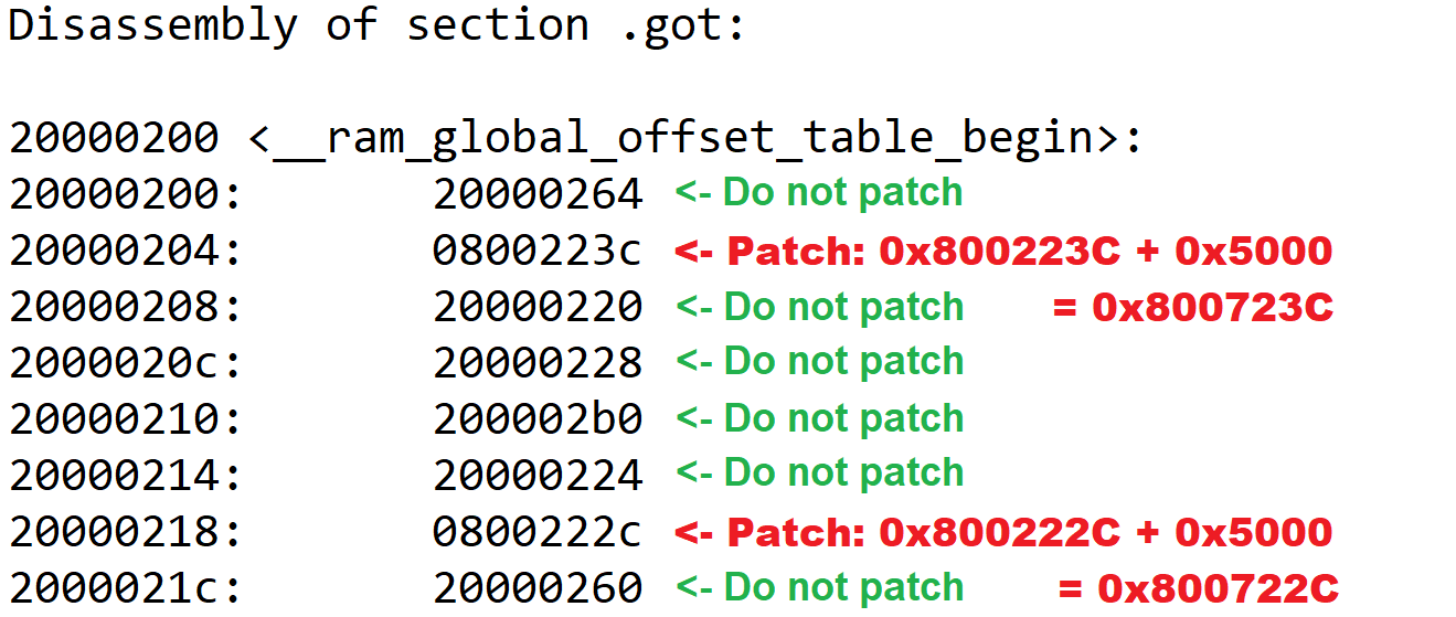
  // GOT needs to be in RAM in every case
GlobalOffsetTableCopyPatchInit:
  movs r0, #0 // Loop variable
  movs r1, #0 // Pointer (just introduction)

GlobalOffsetTableCopyPatchLoopCond:
  ldr r2, =__flash_global_offset_table_begin // Need global offset table table beginning for pointer
  ldr r3, =__flash_global_offset_table_end // And need end for checking loop
  ldr r4, =gu32FirmwareOffset // Need also data offset variable address
  ldr r4, [r4] // And the actual offset value
  adds r2, r2, r4 // Patching flash global offset table begin to honour offset
  adds r3, r3, r4 // Patching flash global offset table end to honour offset
  adds r1, r0, r2 // Pointer value is loop variable + offsetted flash global offset table begin
  cmp r1, r3 // Compare pointer against global offset table flash end
  bhs GlobalOffsetTableCopyPatchEnd // If getting past limits, go to end

GlobalOffsetTableCopyPatchLoopBody:
  ldr r2, [r1] // Load the actual data via pointer
  ldr r3, =__flash_begin // Need flash begin boundary for checking
  ldr r4, =__flash_end // Need also flash end boundary for checking
  cmp r2, r3 // Comparing loaded data to flash begin
  blo GlobalOffsetTableStoreData // If less than flash begin, jump to store
  cmp r2, r4 // Comparing loaded data to flash end
  bhs GlobalOffsetTableStoreData // If more than or equal to end, jump to store

GlobalOffsetTablePatchData:
  ldr r3, =gu32FirmwareOffset // Need data offset variable address
  ldr r3, [r3] // And then the actual data
  adds r2, r2, r3 // Patch the data

GlobalOffsetTableStoreData:
  ldr r3, =__ram_global_offset_table_begin // Get global offset table begin in ram for ram data pointer
  adds r3, r3, r0 // Add loop variable
  str r2, [r3] // Store the data

GlobalOffsetTableLoopIncrements:
  adds r0, r0, #4 // Increment loop
  b GlobalOffsetTableCopyPatchLoopCond // Jump to loop condition checking

GlobalOffsetTableCopyPatchEnd:
  ldr r0, =__ram_global_offset_table_begin
  mov r9, r0 // Stupid trick to put global offset table location to r9, for Cortex-M0
Patching of the Global Offset Table. Why do we need to do this? GOT has multiple addresses. But some addresses point to RAM and only some to flash. We need to patch with offset the values of flash addresses only. This picture hopefully explains:
The final, important line of the assembly code above stores the global offset table to register r9 for referencing.
  // Need to copy and patch vector table in assembly so nobody comes to mess around
VectorTableCopyPatchInit:
  movs r0, #0 // Loop variable
  movs r1, #0 // Pointer (just introduction)

VectorTableCopyPatchLoopCond:
  ldr r2, =__flash_vector_table_begin // Need vector table beginning for pointer
  ldr r3, =__flash_vector_table_end // And need end for checking loop
  ldr r4, =gu32FirmwareOffset // Need also data offset variable address
  ldr r4, [r4] // And the actual offset value
  adds r2, r2, r4 // Patching flash vector table begin to honour offset
  adds r3, r3, r4 // Patching flash vector table end to honour offset
  adds r1, r0, r2 // Pointer value is loop variable + offsetted flash vector table begin
  cmp r1, r3 // Compare pointer against vector table flash end
  bhs VectorTableCopyPatchEnd // If getting past limits, go to end

VectorTableCopyPatchLoopBody:
  ldr r2, [r1] // Load the actual data via pointer
  ldr r3, =__flash_begin // Need flash begin boundary for checking
  ldr r4, =__flash_end // Need also flash end boundary for checking
  cmp r2, r3 // Comparing loaded data to flash begin
  blo VectorTableStoreData // If less than flash begin, jump to store
  cmp r2, r4 // Comparing loaded data to flash end
  bhs VectorTableStoreData // If more than or equal to end, jump to store

VectorTablePatchData:
  ldr r3, =gu32FirmwareOffset // Need data offset variable address
  ldr r3, [r3] // And then the actual data
  adds r2, r2, r3 // Patch the data

VectorTableStoreData:
  ldr r3, =__ram_vector_table_begin // Get vector table begin in ram for ram data pointer
  adds r3, r3, r0 // Add loop variable
  str r2, [r3] // Store the data

VectorTableLoopIncrements:
  adds r0, r0, #4 // Increment loop
  b VectorTableCopyPatchLoopCond // Jump to loop condition checking

VectorTableCopyPatchEnd:
This code does the same to the ISR interrupt vector table. Check picture for reference:

  // Copy the data segment initializers from flash to SRAM
  ldr r0, =_sdata
  ldr r1, =_edata
  ldr r2, =_sidata
  ldr r7, =gu32FirmwareOffset // Load firmware offset variable address
  ldr r7, [r7] // Load the actual firmware offset variable data
  adds r2, r2, r7 // Patch the sidata location with offset
  movs r3, #0
  b LoopCopyDataInit

CopyDataInit:
  ldr r4, [r2, r3]
  str r4, [r0, r3]
  adds r3, r3, #4

LoopCopyDataInit:
  adds r4, r0, r3
  cmp r4, r1
  bcc CopyDataInit
This section copies initialization data (I think like assigned values for variables, etc.) from flash to actual RAM positions. As you can see, we need to offset the load position, here with 0x5000 to get data from correct location in flash.
  // Zero fill the bss segment.
  ldr r2, =_sbss
  ldr r4, =_ebss
  movs r3, #0
  b LoopFillZerobss

FillZerobss:
  // Here we need to check that we are not zeroing out addresses or needed symbols

  ldr r6, =gu32FirmwareAbsPosition // Load address of absolute firmware position variable
  cmp r2, r6 // Compare with what we are going to zero
  beq FillZerobssSkip // If we should skip zeroing, jump away

  ldr r6, =gu32FirmwareOffset // Load address of firmware offset variable
  cmp r2, r6 // Compare with what we are going to zero
  beq FillZerobssSkip // If we should skip zeroing, jump away

  ldr r6, =gu32FirmwareAbsOffsetChecksum // Load address of firmware position and offset checksum
  cmp r2, r6 // Compare with what we are going to zero
  beq FillZerobssSkip // If we should skip zeroing, jump away

  ldr r6, =gu32RamVectorTableBegin // Vector table location in RAM
  cmp r2, r6 // Compare with what we are going to zero
  beq FillZerobssSkip // If we should skip zeroing, jump away

  str r3, [r2] // If not escaped yet, make the store

FillZerobssSkip:
  adds r2, r2, #4

LoopFillZerobss:
  cmp r2, r4
  bcc FillZerobss
Zeroes these variables and data which should have zero initialization value. Here we need to be careful that we don’t zero the global variables we stored the initial register values 😀
  // Call the clock system initialization function.
    bl SystemInit
Calls SystemInit() C function. The function is platform-specific, but at this point it is a good place to set the VTOR register to point to the correct ISR vector location in RAM (Cortex-M4). For Cortex-M0 in this function we remap system memory to achieve same kind of functionality.
  // Make our own __libc_init_array
CallPreinitsInit:
  ldr r7, =gu32FirmwareOffset
  ldr r7, [r7]
  ldr r0, =__preinit_array_start
  adds r0, r7
  ldr r1, =__preinit_array_end
  adds r1, r7

CallPreinitsLoopCond:
  cmp r0, r1
  beq CallPreinitsEnd// If same, it is at end, go away

CallPreinitsLoop:
  ldr r5, =__init_array_start
  ldr r4, =__init_array_end // Yes, order is funny to say the least
  ldr r3, [r0]
  push {r0, r1, r2, r3, r4, r5, r6, r7} // Save context because calling externals
  blx r3
  pop {r0, r1, r2, r3, r4, r5, r6, r7} // Retrieve context
  adds r0, r0, #4
  b CallPreinitsLoopCond

CallPreinitsEnd:
  ldr r3, =_init
  adds r3, r7
  ldr r5, =__init_array_start
  adds r5, r7
  ldr r4, =__init_array_end
  adds r4, r7
  push {r0, r1, r2, r3, r4, r5, r6, r7} // Save context because calling externals
  blx r3
  pop {r0, r1, r2, r3, r4, r5, r6, r7} // Retrieve context

CallInitsInit:
  ldr r7, =gu32FirmwareOffset
  ldr r7, [r7]

CallInitsLoopCond:
  cmp r5, r4
  beq CallInitsEnd

CallInitsLoop:
  ldr r3, [r5]
  add r3, r3, r7
  push {r0, r1, r2, r3, r4, r5, r6, r7} // Save context because calling externals
  blx r3
  pop {r0, r1, r2, r3, r4, r5, r6, r7} // Retrieve context
  adds r5, r5, #4
  b CallInitsLoopCond

CallInitsEnd:
Final part of the assembly routine recreates an assembly function __libc_init_array because the original binary-only library function would fetch data from wrong location.
Utilizing this whole orchestra of linker script modifications, compiler options and this assembly code makes it possible for the firmware image to actually boot from anywhere 4-byte aligned addresses! And it is even portable between Cortex-M0 and Cortex-M4; I’m actually using the same files for bootloader scan/jump and the assembly start routine for both.
Demonstration
I created a demonstration video showing how the Cortex-M4 variant works. Check it out!
Benefits and cool features of the described Position-Independent Code firmware image system
There are multiple cool things and benefits about the system I have developed. I’m listing them here.
Full portability
By using careful approach and meticulous testing, the flash functions and assembly startup code are fully portable between ARM cores. Cortex-M0 and Cortex-M4 have been tested and they work fine.
Working and tested interrupts, static and global variables
The firmware LED blinking functionality is achieved by using interrupts. This demonstrates that the relocated ISR vector table is working just fine. As static and global variables also work, we can conclude that the global offset table is also working as it should
Keeping bootloader dumb
One problematic thing earlier about people describing bootloaders is that they have implemented complex firmware patching functionalities already there in the bootloader. This is the wrong approach, as I described in my earlier post. In this bootloader I merely scan the flash and jump if something is found. I just add one offset before the jump. This keeps things very simple. Also, firmware knows best how to bootstrap itself, not the bootloader.
Firmware is able to run from any 4-byte aligned flash position and save space
In linker script we made the smart move of saving a dedicated space from the beginning of RAM for the ISR interrupt vector table. This makes it possible to place the firmware in any 4-byte aligned flash position. Because the data goes to the beginning of RAM eventually, it is naturally 512-byte aligned and all is well. If we did uniform forcing of 512-byte boundary without really thinking, we could have been wasting space when combined with other techniques, like the dynamic header.
Possibility to run the firmware standalone
It is also possible to run the firmware standalone, for example from 0x8000000. This way we don’t need to run through esoteric hoops during debugging, we can debug the software as if it was a normal piece of software. When we are later ready, we can move on to test functionality in relocated state.
Integrated mass erase in toolchain for flashing
A mass erase command has finally been integrated into the IDE toolchain. This way we can be sure there are no remnants of earlier firmware images in the flash. These remnants, when unnoticed otherwise, can look like extremely esoteric bugs happening. Or not happening.
Thorough documentation
As I wrote earlier, I am probably the only human on Earth to publicly provide verbatim, working example code and fully document what every part does and why. In a system like this trying to make everything as understandable as possible is an absolute must.
Caveats
In general I don’t have further knowledge about constraints for using the system described here. Old hearsay is that there can be problems with function pointers. What I remember reading is that C++ can also be problematic. But as of 2022-01-17 I have had no time to verify the claims. I verified today finally that the fourth compiler option was needed for static variables to work.
Also in general, it is possible that when in IDE debugger, for example hovering the mouse over variables, especially GOT-related variables, you might get wrong initial impression about their values. In instruction stepping mode however one can verify that situation is normal and variable contents are as they should be.
There is one problem, which came evident after a reader contacted me. He had included a binary library in his project. This inclusion made the MCU crash. The thing is, the library was overwriting r9. This caused a crash. I don’t know if we could have used some kind of trickery to restore r9 afterwards. Maybe, maybe not. But the thing is: Every binary library you include is basically a black box. If you can rebuild the library yourself, you should in compiler options reserve the r9.
Notes about flashing
In the provided project files the addresses for flashing images via IDE are currently configured as follows:
- Bootloader: 0x8000000
- Main firmware image: 0x8005204
Location of bootloader is quite the non-brainer. The esoteric location for main firmware is chosen in order to create “worst case situation” of sorts.
If flashing using external flasher, this order must be followed:
- Mass erase the whole flash
- Flash bootloader to 0x8000000
- Flash firmware image to any location beginning from 0x8005000 and aligned to 4-byte boundary.
Also, it is recommended to use the .bin files for flashing as they don’t contain confusing address information. As told earlier, mass erase is important! Otherwise it may be that program is only accidentally working because it sees data from locations that should be empty actually. So situation without mass erase can create seemingly working “no-bug” situations, masking actual bugs.
Closing words
I hope you enjoyed my finding. I really poured my heart into this research for the last 6 months. In case you need an engineer to implement software update for your ARM products, I am occasionally available for hire. See my contact info below.
Its very interesting to see your post .
How you have handled PLT ?
Hello. Unfortunately I have not the slightest idea about PLT 😀 Maybe other people have made better posts about it.
Hi janne,
I confirm you that if in your code there is a table (not const) with function pointers the compiler doesn’t generate any in GOT or in PLT but store the raw funcion address into data section.
Ciao,
Gianluca
Thank you! This is most valuable information.
But there is a chance: all data sections where there are variables, struct, array that contain function pointers or (more in general) pointer have “name” .data.rel.XXX in this way there is possibile to identify (not so simple as with GOT) and change the address of these pointers.
Hi Janne,
Thanks for your sharing, it’s very cool, now I’m trying to port your code to my demo project which is used for the i.MX RT1050 (bases on the Cortex-M7), unfortunately, it still not succeed, as the GCC compiler can’t identify gu32FirmwareAbsPosition,gu32FirmwareOffset, gu32FirmwareAbsOffsetChecksum in the fw_anywhere_startup_inline.S,
Further, my IDE is MCUXpresso which seems like a variant of the Eclipse, it will contain the below library in default.
“libcr_c.a”
“libcr_eabihelpers.a”
“libgcc.a”
Should I modify the part of the assembly routine that recreates an assembly function __libc_init_array?
BR,
Jeremy
Hello,
(I have zero experience with MCUXpresso, but I will try to help.)
First you need to make it able to compile. You need these in your project: image_info.c image_info.h
See:
https://github.com/usvi/L432KC-BL-FW/blob/master/L432KC_Firmware_anywhere_STM32CubeIDE/Core/Inc/image_info.h
https://github.com/usvi/L432KC-BL-FW/blob/master/L432KC_Firmware_anywhere_STM32CubeIDE/Core/Src/image_info.c
Try to get it to compile first. Then check back with the rest, ok?
Hi Janne,
After adding the image_info.c image_info.h, the compiler won’t report the error, however, I’m still confused with that and hope you can clarify it.
I check the map file in your application demo, the gu32FirmwareAbsPosition,gu32FirmwareOffset, gu32FirmwareAbsOffsetChecksum should belong to the bss section, so I suspect whether it’s Okay prior to copying the bss section from the Flash to RAM.
And I have another question about the below code,
CallPreinitsEnd:
ldr r3, =_init
adds r3, r7
ldr r5, =__init_array_start
adds r5, r7
ldr r4, =__init_array_end
adds r4, r7
push {r0, r1, r2, r3, r4, r5, r6, r7} // Save context because calling externals
blx r3
pop {r0, r1, r2, r3, r4, r5, r6, r7} // Retrieve context
the compiler reports an undefined reference to `_init’, and I also did not find the declaration of the `_init’ in the application project.
BR,
Jeremy
Hello Jeremy. And sorry for my long delay. I am finally on vacation and can think about this “hobby” thing.
“I check the map file in your application demo, the gu32FirmwareAbsPosition,gu32FirmwareOffset, gu32FirmwareAbsOffsetChecksum should belong to the bss section, so I suspect whether it’s Okay prior to copying the bss section from the Flash to RAM.”
I hope I can clarify this. I have modified the stock STM32 startup assembly / C environment bootstrap routines a bit. The original routines copy (and zero when needed) everything relevant from flash to RAM verbatim. But I have made few changes:
0. Store register values passed by bootloader to gu32Firmware* variables
1. Use proper offsets when copying / zeroing variables or preparing the GOT
2. When copying / zeroing, explicitly AVOID zeroing all the gu32Firmware* variables because we need to have FULL CONTROL of the contents
To get full control, we do operations in assembly so GCC does not try to use the GOT for these important variables. Other variables (in C) are just fine to be handled with GOT/PIC mechanisms.
“the compiler reports an undefined reference to `_init’, and I also did not find the declaration of the `_init’ in the application project.”
This is because the startup routines are different for every IDE. You need to:
1. Figure out what assembly startup routines are used
2. Store bootloader-passed register values as gu32Firmware* variables
3. Modify routines to add offsets when needed
4. Modify routines to avoid zeroing gu32Firmware* variables
5. Patch GOT addresses when needed
This is how it in general works. Sometimes, if you have “black box libraries”, it might be hard to set this completely up. The less libraries, the better/easier it is to set up.
BTW, what evaluation board are you using?
I try to run it on the stm32f103rb, but without success. It seems like the bootloader finds the app at the correct address, but after the jump to the main app nothing happens, the main app doesn’t start. If I upload the main app at the 0x8000000 address, it works correctly, but only then, at any different address it doesn’t start. What do you recommend to check first?
I suggest you use EXTERNAL programmer. Do like this:
1. Full erase
2. Flash bootloader .bin only to 0x8000000
3. Check that bootloader works (LED changes state)
4. Flash application .bin to for example 0x8005000 and DO NOT ERASE ANYTHING EXTRA
5. Disconnect the chip, connect it without debugger
6. Check that first bootloader works as in 3., then see that the speed of the LED changes as application runs
Hi,
Nice post. I have ported this to a NXP LPC804 with some other code, and it is almost working.
Code is running fine, but when an interrupt (in this case UART) kicks in, It jump to the linked address and not the address + offset. Any Ideas what can be wrong?
Hello. I think you have maybe failed to properly patch the .isr_vector entries. Maybe a variable you are using as an offset is zero by mistake? Step carefully those parts of the assembly.
Btw, are you sure your GOT patching is working with relocated firmware image? You can check by temporarily disabling interrupt functionality in your code.
Get back to me, I’m interested in hearing more.
Hello,
(Seems my 1st post was not post. sorry if it is double)
Thank you for this work. It is really interesting! I’m trying to make it work on a Cortex-M7 (STM32F767) with no succes for now. The bootloader work fine and jump to the application, but nothing append after that.
I’m checking everything in the application projet. I have seen that the RAM_ISR_LEN is not the same on Cortex-M0 and Cortex-M4 (seen in the .LD of your booth project)
Do you know what is the size of RAM_ISR_LEN on a Cortex-M7? I haven’t find it so far…
Thank you
Hello. This information is normally listed in some kind of architecture manual
I found it here: https://developer.arm.com/documentation/dui0646/b/BABIFJFG
Table size is 0x03FC + 0x4 = 0x400 = 1024 (dec). Checks out.
So indeed the table size was different. I hope you can get your project to forward with this.
Thanks for a very interesting read!
I have finally wrapped my head around all this after some intense hours. Basically, what you have done is that you have planted mines for the future because this won’t work in a reliable way. GOT doesn’t solve all your problems, the only thing it does is that it lets you have a dedicated area for variable lookup so that you don’t have to have absolute addresses embedded inside your code. By going through the GOT and determining if the variable is located in RAM or FLASH by looking at the address, you have managed to relocate some of the information… However, that’s the only thing you will be able to patch.
What the patch above does is that it patches the addresses that the compiler needs to use to do it’s thing, however, this is NOT the same as data. All data that is not in the bss section has some kind of initialised value wether it’s constant or modifiable. Since this is pure data, you have no clue wether it’s an address or just a value when you just look at the data inside the data section or rodata section.
If you have global pointer to anything that’s inside the flash memory, e.g. a pointer that points to anything in the text section or rodata section, what your GOT is helping you with is to determine where the pointer is stored. Once you have the location of the pointer, the value of the pointer is a completely different thing. Nevertheless, if it points to something in the RAM area, then it isn’t game over because that will actually work since you’re not relocating the RAM area. However, every pointer value that is pointing to something inside the text section or rodata section will be corrupt if you load your image to a different address than the one used when you statically compiled your binary.
That said, what GOT helps you with is to make your code position independent but *not* your data. So for pointers pointing at anything constant, may it be a variable or function pointer… all these pointers will be corrupt after any relocation.
Anyway, it was a good exercise to understand all this, thank you for sharing.
Thank you for your in-depth comment. I need to study it thoroughly. I might need to add a big fat warning about the behavior. But it is a good thing this is now as a comment.
If you have time, I’d like to have a chat some day. I’m on LinkedIn : https://www.linkedin.com/in/janne-paalijarvi/ or on IRC Libera as usvi
Thanks a bunch.
Feel free to drop me a mail, I am gladly discussing this further!
Hi,
Thanks for this cool project. I have ported this to M0+ and M7 and it’s working correctly. The only thing is that as mentioned above, some constants can get corrupted, especially tables or strings so the workaround is to declare it as non-read-only data.
The only issue I have is debugging the main application as the Nucleo board I am using comes with ST-Link and if I configure my main application to be downloaded at a specific address let’s say 0x8005000, STM32CubeIde still tries to debug from 0x8000000. What is the programmer do you use for debugging?
Nice to hear about porting.
It has been some time since I worked on this, but. I have recently used the cube programmer because I have not worked in IDE lately. But I think when I was debugging, I programmed bootloader to 0x8000000, then main application to 0x8005000, then started debug from 0x8000000 => bootloader ran => switched to main application and I somehow operated there. This is just out of my hazy memory and needs verification.
Hi,
I’m trying to port Your Project for M3 (STM32F207). Unfortunately I have some problem with function pointers :(.
The main programm starts correctly (All of the assembler patches where OK) but at the moment, a function stored as a function pointer shall start, the program tries to start it from a non patched address.
Can You give some hint, how to make an override? (Theoretically I can store the offset and add it on each function pointer, but it is ugly.. )
Hi,
Thanks for the blog. I ported all on cortex m7 and its working fine. Just only below line not working and getting stucked at hardfault.
sprintf(tick_string, “Test”); // working fine
snprintf(tick_string, sizeof(tick_string), “%d”, 1234); //getting stucked at hardfault
Any one face this issue. Please let me know. I need help at this point. Could not understand how to debug?