IT System Design 101: Decoupling of address and entity data in a self-addressing bus

There exists a special use-case for data handling in a situation where multiple self-addressing devices are using the same bus for communication. In the common case self-addressing devices work as follows:

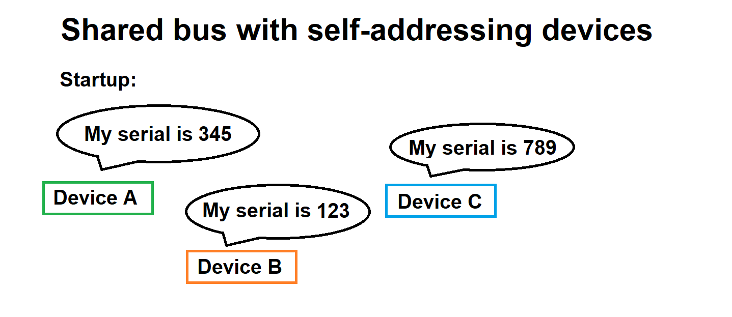
  1. Each device has hardcoded unique piece of information to be used as a seed value for addressing (lets call this “serial number” for simplicity)
  2. Upon powering up, the devices negotiate with each other, either on the common bus (think application CanBUS) or nondocumented/out-of-band means
  3. During the negotiations, the devices agree about bus addresses of each device, based on presence of each device and everyone’s serial

Self-addressing bus is presented briefly in the image below.

Okay, so far so good. But what happens if the number of devices on the bus changes? There are multiple ways to deal with the situation. In case of new devices, one possibility is to assign the new devices with next, unused bus addresses. But how about when we lose devices? Should we just drop those bus addresses and be happy with it? There is no one size fits all -solution for the total problem, but a reasonable solution for situations where the number of devices is comparably small is to always re-negotiate the bus addresses. Another possibility is to regard missing devices as missing but in-place and re-negotiate only if the new device takes a bus address already in use.

Identifying a bus address change can be made with a couple of techniques. One possibility is to have a register status bit announce a change condition. Another possibility is to send announcement messages for a sufficient amount of time. External shared DIO can also be used in some contexts. And of course, there is the pathological case of reading all serial numbers during all communication rounds, but this is usually something we should try to avoid, and especially if we are designing the actual bus operation.

Let’s define next what is bus data and device address in a self-addressing bus. Bus data is verbatim, contemporary data read from a device on the bus. The bus data can tell it came from a certain bus address, but it cannot directly tell that it came from a certain physical device (though this information is attainable). Device address is something allocated by the system controlling the devices. It is semi-permanent, conceptual address we use in consistently in user interfaces to differentiate between devices. To recap:

  1. Device address is used for user interfaces, does not change in practice
  2. Bus address is somewhat volatile indication of where the current bus data came from
  3. Bus data is various readouts from the device (like voltage, power, etc)

Let’s make short example to clarify how bus address change happens. Let’s say we first have device A with bus address 1. Now, device B comes present on the bus and devices re-negotiate their bus addresses. Device B now gets bus address 1. Device A will switch from bus address 1 to bus address 2. Any cached bus address 1 data needs to be properly invalidated or repurposed.

We have now somewhat adequately described what is bus data and how does it react to address changes. But to make it very clear, we should regard bus data as volatile information, something we might not be able to re-read in the future, rendering the old data outdated. So, what is the non-volatile version of bus data? We can call it device data, or if we want to put it more finely, entity data. In normal operation, device data is linked to bus data. This glue mechanism is called inventory. The linking of bus data to device data is maintained by keeping a record of device serial number in device data. We also have a placeholder for the serial number in bus data (we read serial number bus data only when there is an address change situation).

Small sketch of inventory system managing bus and device data is presented below.

Now, in the event of addressing changes in the system the following happens:

  1. All links between all bus data and device data are cut
  2. Bus data is zeroed so it does not cause trouble or confusion
  3. Complete bus data is read from all available device address
  4. Serial numbers between device data and bus data are compared; if there is a match, bus data and device data are linked
  5. Special cases are handled

Let’s finally list some of the special cases and the accompanied actions

  • New device appears on bus => If there is space, allocate new device address
  • Device leaves bus => Keep device data and device address, but mark device non-communicating
  • New device replaces old device => Ask user to acknowledge configuring to new device as the old device was
  • System startup => Request a mapping of device addresses, serial numbers, and configuration data, then scan bus devices and if the same serial numbers are found, configure the devices accordingly

With all the previous stated we have covered majority of decoupling address and entity/device data in a self-addressing bus environment. We learned that bus data can become obsolete fast and that the real device data should be kept on a separate data structure, with 2-way links between device data and bus data. We also learned about addressing change circumstances and the special cases involved with them.

Epoll tutorial and understanding the overlooked epoll_data_t

Epoll is a mechanism of Linux Kernel / Linux C runtime to monitor multiple file descriptors for I/O. Lets say you have a server program which has open connections as file descriptors. Epoll mechanism offers more performant “watching” of all these file descriptors for activity compared to some other options, like select(). Some tutorials about epoll exist on the internet, but many fail to acknowledge WHY what is happening is actually happening. So allow me to walk you through with this small example program utilizing epoll.

Continue reading “Epoll tutorial and understanding the overlooked epoll_data_t”

Portable Position-Independent Code (PIC) bootloader and firmware for ARM Cortex-M0 and Cortex-M4

Disclaimer 2024-05-07

Although PIC was a very interesting trek in the deep embedded territory, I’m not that confident about the benefits as of today, 2024-05-07. See the comment below from “manne”.  He discovered that even though some aspects of my solution works, it is basically unusable in the comprehensive scale. Therefore, for the time being, I am discouraging people from using PIC in real-world applications, and only exploring the subject for academic interest. I will write later more in-depth analysis of shortcomings and will also propose some compiler changes to tackle the main issue and also some some generic PIC optimizations.

Rest of the text is kept for posterity.

How to implement Position-Independent Code for microcontroller (MCUs) is a question which has been asked countless and countless of times all over the Internet. The answers and “solutions” are usually whippersnappering comments dropping a couple of key terms they probably just googled up without any kind of intrinsic knowledge about how the system should be working.

Sometimes the answer is “OK I got it working” followed by eternal silence from people asking clarifications. In other words, it looks like the task is very difficult and once people get it to work, it is so valuable they want to hide the details. In a way I cannot blame them much; it took me 6 months of half-time work every now and then to understand everything.

So, some 6 months ago I set myself a goal: “Create a portable solution where an intelligent bootloader can boot firmware images from any address in flash on Cortex-M0 or Cortex-M4 platform.” Finally, as of today 2022-01-16, I consider I have solved the problem in an intelligent and understandable way.

Funnily, I think I am the only person on planet Earth who has made available readily working example code and documented the code in a way I am doing now in this post.

Those impatient can explore the fully working STM32CubeIde codes at GitHub, for Cortex-M0: https://github.com/usvi/F070RB-BL-FW  and for Cortex-M4: https://github.com/usvi/L432KC-BL-FW  . (One might ask why one would use this kind of bloated stock configuration for developing on MCUs. Believe me, I’m doing it here only for pedagogical reasons. This way it is easier for noobs having the needed evaluation boards to verify that the code is working.)

The set of code I have created is a proof-of-concept, working for the C language. There might, and I underline, might be unforeseen problems when amount of global variable gets absurdly high. In any case, comments and criticism is more than welcome.

If you are ready to dive into the deep end of Cortex-M boot process, PIC constructs, esoteric debugging and linker script optimizations, continue reading…

Continue reading “Portable Position-Independent Code (PIC) bootloader and firmware for ARM Cortex-M0 and Cortex-M4”
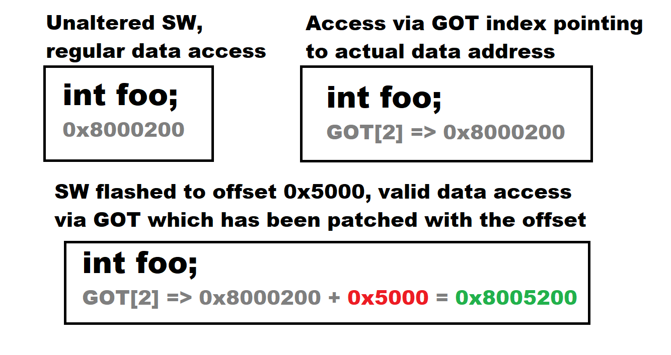
Primer and use case of Position-Independent Code in ARM Cortex-M MCU environment

Recently I described my friend that I was working with Position-Independent Code on a Cortex-M0 and Cortex-M4 environment. To my surprise, he was more interested about “why” and not “how”. I think before revealing the nitty-gritty details of this domain, I can give readers an overview about things.

Continue reading “Primer and use case of Position-Independent Code in ARM Cortex-M MCU environment”

Firmware interrupt vector table relocation by bootloader considered harmful

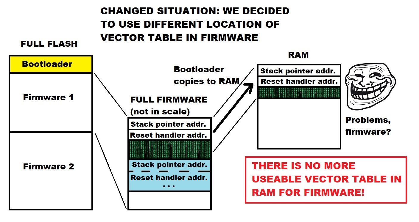
I have developed in the past month or so a way to have position-independent-code (PIC) firmware image (on ARM Cortex-M0 and Cortex-M4) which can be put (almost) anywhere in flash. I’m still refining the concept and will write an in-depth-article about it. There is a part of the PIC stuff that I can discuss briefly to get us going about THIS article.

Part of the PIC firmware + bootloader has been interrupt vector table relocation. Basically the bootloader needs to read from flash the firmware vector table and copy it to RAM and then point the MCU to use the vector table from RAM. Some of tutorials, videos and comments suggest that bootloader should do the relocation. I have, however, come to the conclusion that this is actually wrong way to proceed. I will try to demonstrate now why.

Continue reading “Firmware interrupt vector table relocation by bootloader considered harmful”

Dynamically generated MCU binary image header (Arm Cortex-M4)

Every seasoned embedded systems engineer faces at some point of their career a problem about needing to put a header to their built firmware image binaries. This header usually contains at least information about what device the image is for and what version number the image is. Checksums are also common.

There are multiple ways of implementing the header. One solution is to just glue it on top of the image and peel it off while updating the firmware via IAP or external programmer means.

Another approach is to place it actually in firmware flash, to a known location, possibly even start of the image, but use a bootloader to jump past the header.

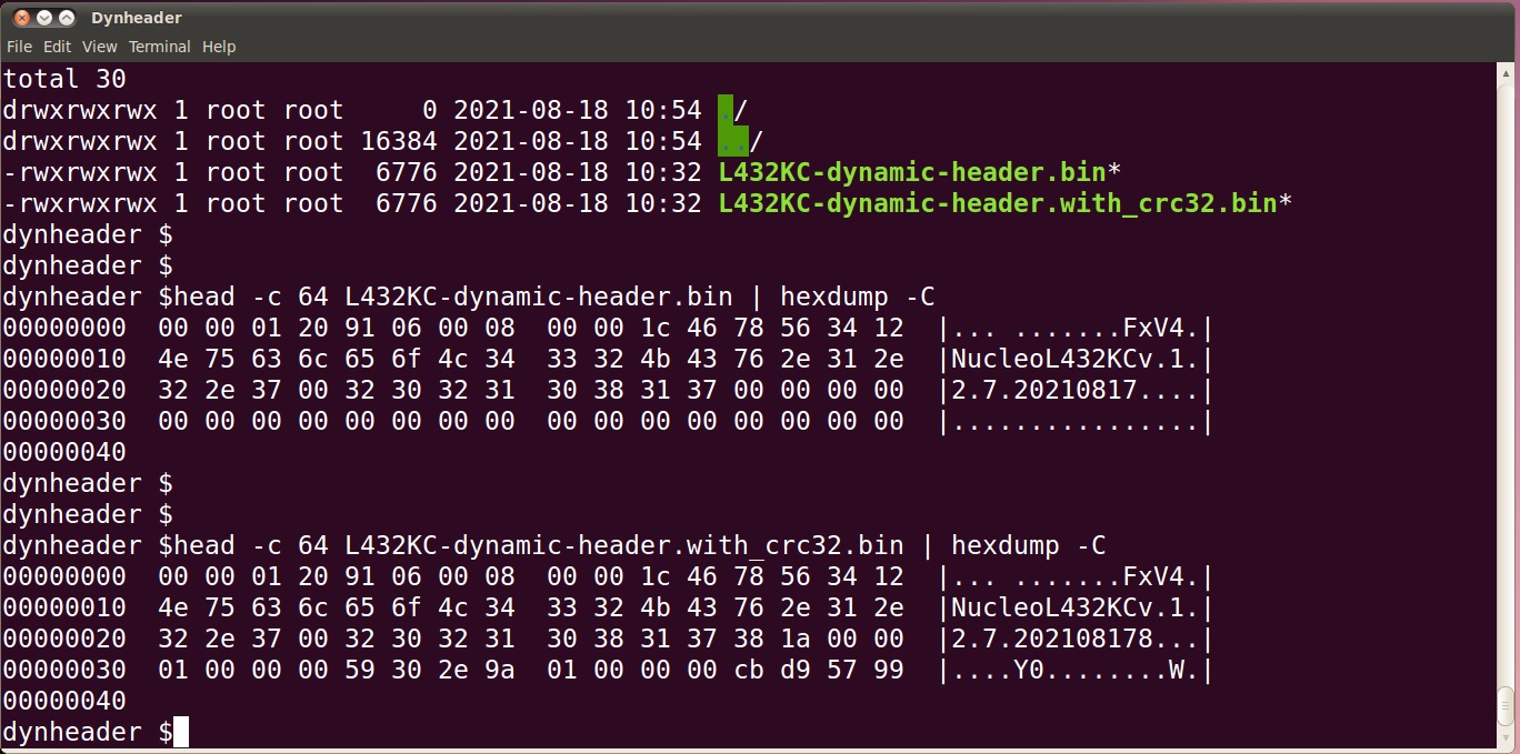
There is however yet another solution I’m going to demonstrate. It is about generating the header template directly into the flash image, and even surprisingly in a way that the MCU can start executing actually from the beginning of the header (template). An external tool is used later to fill in checksum data.

But before continuing, heres a big fat warning:

WE ARE MANIPULATING VECTOR TABLE OFFSETS WHICH IS CONSIDERED DANGEROUS PRACTICE REGARDING ULTIMATE RELIABILITY OF THE RUNNING CODE. YOU HAVE BEEN WARNED.

There. Now lets go on.

We will be working on our trusty old STM32 Nucleo-L432KC and STM32CubeIDE. Example codes are available at https://github.com/usvi/L432KC-dynamic-header .

Continue reading “Dynamically generated MCU binary image header (Arm Cortex-M4)”

Properly offsetting relocated (Arm Cortex-M4) code in STM32CubeIDE GDB

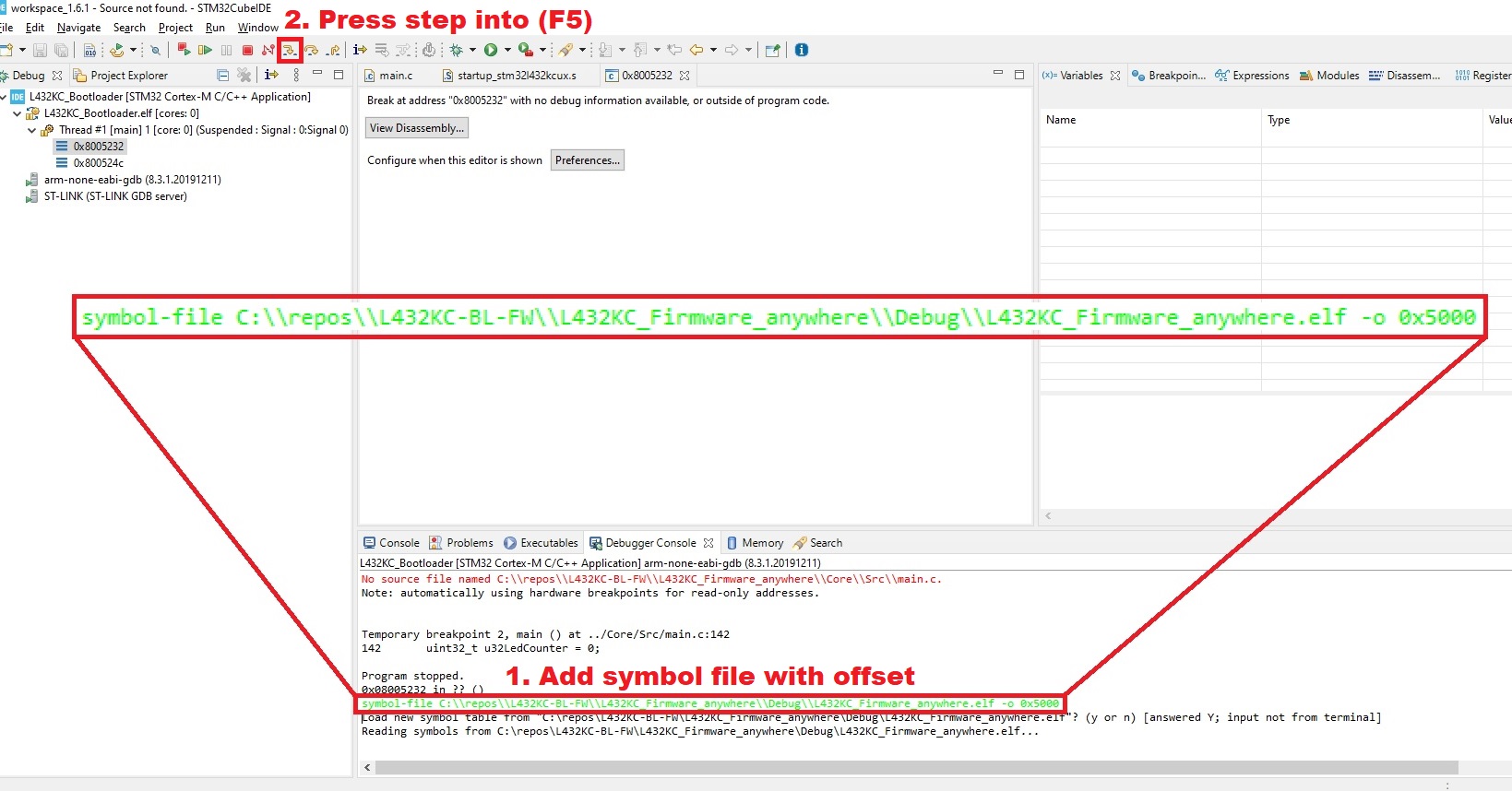
In my previous post I was showing a very elementary but outright inefficient way to debug tricky (Arm Cortex-M4) code which was relocated. The full case was/is: There is a bootloader which loads actual firmware binary. Bootloader is at 0x8000000, firmware at 0x8005000. We used a method to load debug values to registers we were monitoring. It worked but was complex and did not address the root cause of mismatched symbols. There is however a way to make the relocated firmware binary to correspond 100% to the debug symbols and debugger screen. Read below to know more.

Continue reading “Properly offsetting relocated (Arm Cortex-M4) code in STM32CubeIDE GDB”

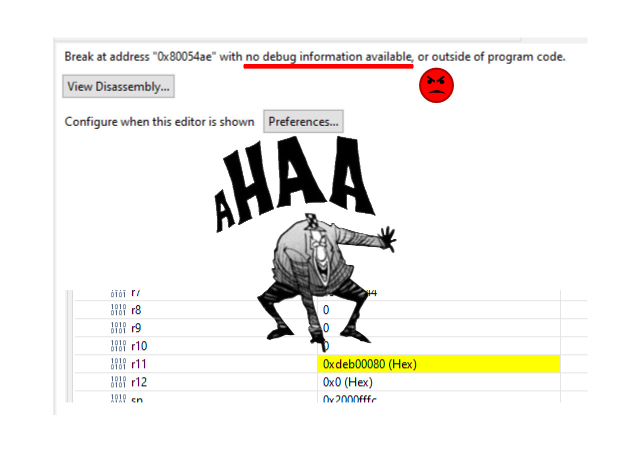
Debugging tricky (Arm Cortex-M4) code with register values

Sometimes you may run into problems when debugging tricky code. This is the case especially with microcontroller code if you are implementing a bootloader+firmware image solution. Debugger started in bootloader goes haywire and displays garbage or nothing at all when jumping to firmware.

Normally one should invest some time in getting debugger symbols aligned properly with source code, but if there are for example some barring deficiencies in environment or debugger UI, one can still figure out a bit more what is going on by using spare register values. Following shows a somewhat obvious, but still possibly helpful technique in brief for aforementioned debugging situations.

UPDATE 2021-08-16:
To get the job actually done, see my follow-up post

But in any case, the rest of the earlier post is here for posterity.

Continue reading “Debugging tricky (Arm Cortex-M4) code with register values”

LEGACY Crash Course in Debugging C Programs with Emacs GDB (annotate=3)

I have a constant need to debug specific C programs. Because I have mostly worked in constrained embedded systems Linux environments, in reality I have not had possibility to have a debugger available. So I never learned GDB. But recently I was able to compile the application binaries in a regular 32-bit Linux environment. I was finally able to do debugging with Emacs GDB after learning just one day. This crash course will probably help you if you want to learn GDB debugging with text mode Emacs. We will be using the gdb-many-windows variant layout.

Continue reading “LEGACY Crash Course in Debugging C Programs with Emacs GDB (annotate=3)”